Recoil system

US7685755B1Inactive Publication Date: 2010-03-30VISTA OUTDOOR OPERATIONS

Image

  • Recoil system
  • Recoil system
  • Recoil system

Examples


Embodiment Construction

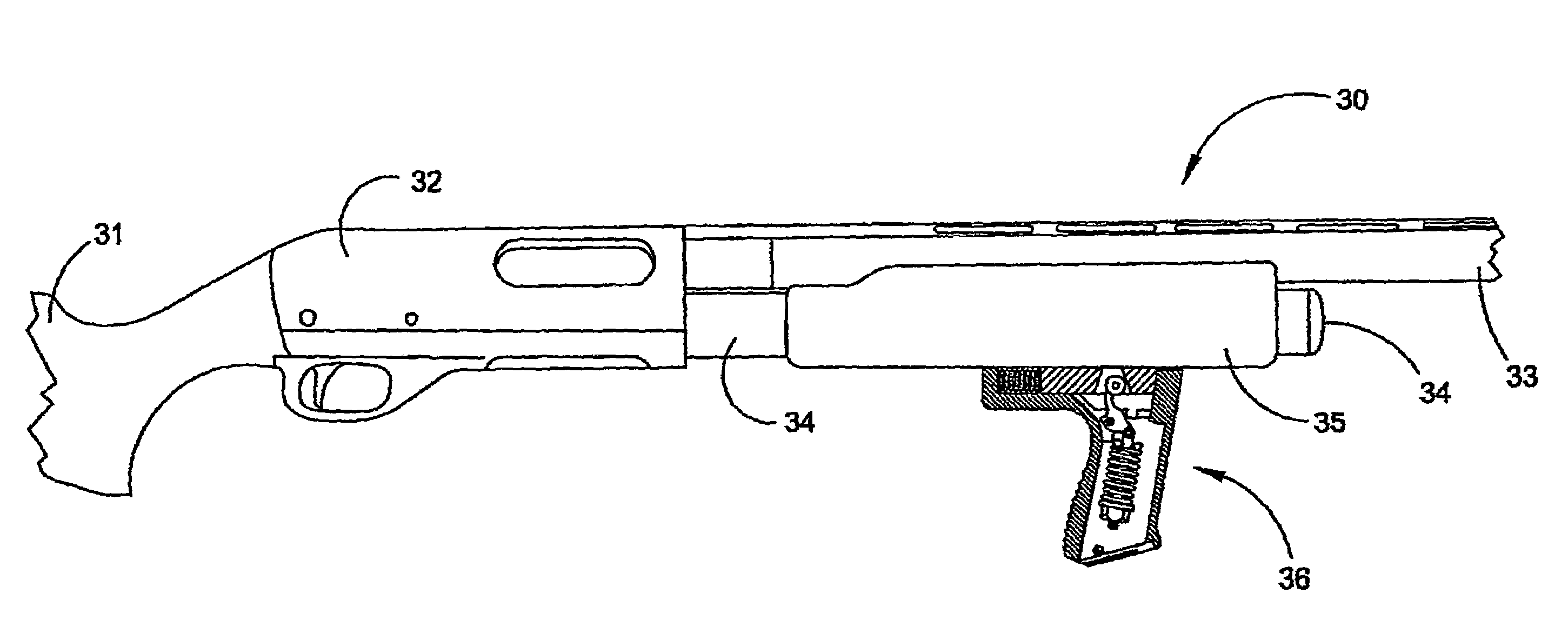
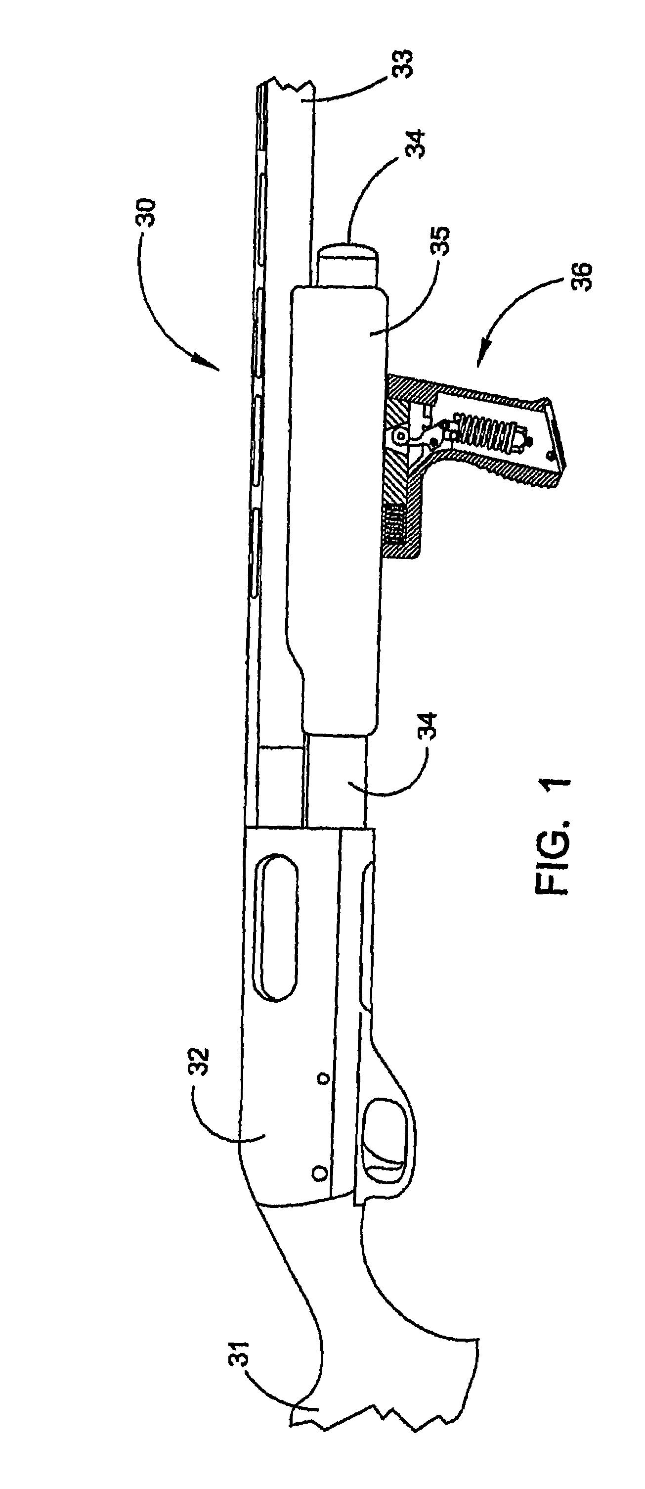
[0050]The novel recoil reduction system for a firearm will now be described by referring to FIGS. 1-9 and 18-19. A shotgun 30 is illustrated in FIG. 1 having butt stock 31, a receiver 32, a gun barrel 33, a magazine 34, a forend 35 and a handgrip member 36. The recoil reduction system is mounted within handgrip member 36.

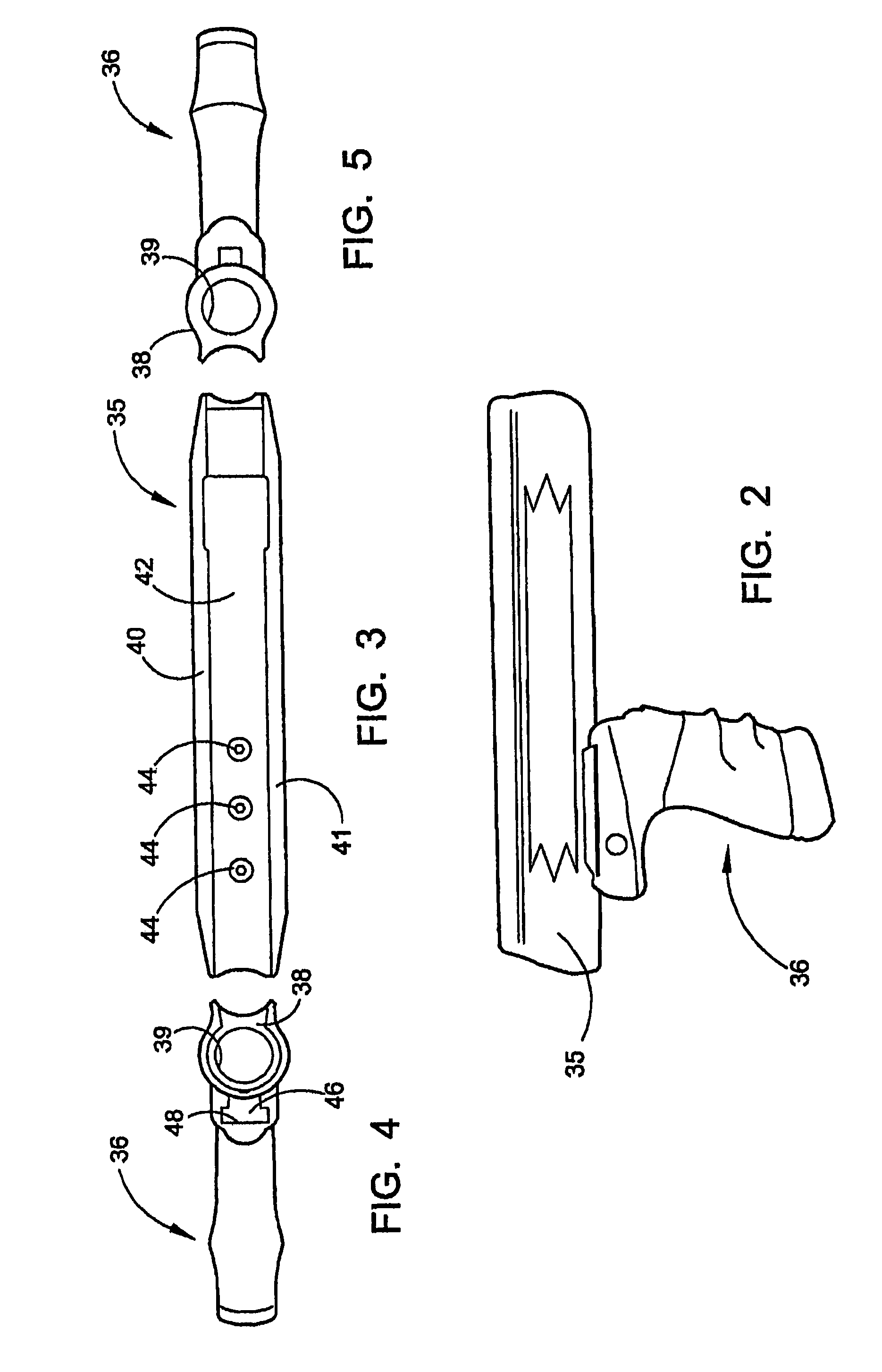
[0051]FIGS. 2-5 and 18-19 illustrate views of the forend 35 from various sides and angles.

[0052]FIG. 4 is a rear elevation view and it shows that forend 35 has a generally U-shaped transverse profile with a ring 38 formed at its front end. Ring 38 has a bore hole 39 that would telescope over magazine 34. The remainder of forend 35 has a left side wall 40, a right side wall 41, and a bottom wall 42. A plurality of screws 44 secure an inverted T-shaped rail 46 to the bottom surface of forend 35. Handgrip member 36 has a longitudinally extending inverted T-shaped track 48 along which rail 46 reciprocally travels. Track 48 has a chamber 49 formed in its rear end that re...


PUM


Abstract

A recoil reduction system having an elongated forend portion having a front end, a rear end, a left side wall, a right side wall and a bottom wall; and recoil reduction means attached to said forend, wherein said recoil reduction means further comprises a longitudinally extending rail extending downwardly from a bottom surface of said forend portion; and an upright oriented handgrip having a top end, a bottom end, a front end, and a primary chamber that extends upwardly within said handgrip, wherein a track is formed in said top end of said handgrip, wherein said rail is slidably received in said track to support said handgrip, and wherein said recoil reduction means is mounted in said primary chamber of said handgrip.

Description

CROSS-REFERENCE TO RELATED APPLICATIONS[0001]This is a Continuation-In-Part of U.S. patent application Ser. No. 11 / 132,872, filed May 19, 2005, now U.S. Pat. No. 7,340,857, the disclosure of which is incorporated herein by reference.BACKGROUND OF THE INVENTION[0002]1. Field of the Invention[0003]The present invention is directed generally to a recoil reduction system. More specifically, the present invention is directed to a recoil reduction system that is attached are coupled to or embedded within the forearm of a firearm or other device.[0004]2. Description of Related Art[0005]One age-old problem that has existed with firearms or other similar devices is the fact that many of them have a severe recoil that affects the person firing the weapon. In firearms such as shotguns and rifles, the rear end of the butt stock is positioned against the shooter's shoulder and recoil often causes the shooter to raise the front of the firearm each time the weapon is fired. Also recoil varies depe...

Claims


Application Information

Patent Timeline
30 Mar 2010
Publication
US7685755B1
IPC
F41C23/16; F41A25/00
CPC
F41A25/10; F41C23/06; F41C23/16; F41G11/003
Inventors
BENTLEY, JAMES K.