Ceiling light fixture adaptable to various lamp assemblies

a technology for ceiling lights and lamp assemblies, applied in lighting applications, lighting support devices, lighting and heating apparatuses, etc., can solve the problems of inability to immediately replace lamp tubes that are already in the stock of these companies or organizations, and the replacement can only be done in a gradual, step-by-step process in a very long course of time, so as to achieve efficient repairing, reduce waste, and reduce the effect of light fixtures

Inactive Publication Date: 2010-03-30
VALENS
View PDF7 Cites 70 Cited by
  • Summary
  • Abstract
  • Description
  • Claims
  • Application Information

AI Technical Summary

Benefits of technology

[0008]The primary purpose of the present invention is to provide a ceiling light fixture adapted to interchangeably use with various lamp assemblies, comprising a base housing forming at least one elongated channel having a trapezoidal cross section and light-transmitting cover panel corresponding to each elongated channel and having edge plates forming tenon fitting structures for closing an opening of the channel. Each trapezoidal-cross-section channel has a bottom wall forming an elongate slot. The bottom wall of the trapezoidal-cross-section elongated channel that forms the elongate slot forms on a back side thereof a circumferential raised mounting frame and a plurality of barbs extending from the mounting frame. The bottom wall of the trapezoidal-cross-section elongated channel further forms in each lengthwise end with respect to the elongate slot a lamp tube end seat fitting hole. Thus, the ceiling light fixture selectively allows a first, electronic light source based lamp assembly carrier board to be removably received in the mounting frame and clamped and secured by the barbs to have the electronic light source exposed through the elongate slot for irradiating light toward side walls of the trapezoidal-cross-section elongated channel and the light-transmitting cover panel and or alternatively allows a lamp tube end seat to be fit and retained in the lamp tube end seat fitting hole to set and fix a lamp tube of a second lamp assembly in the elongate slot to realize interchangeable use of the ceiling light fixture with different lamp assemblies. In this way, there is no need to discard the original light fixture in adapting different, new light sources and the amount of waste produced by discarding the original, but still workable, light fixture can be substantially reduced.
[0009]Most of companies or organizations are operated in such a way that they keep a stock of consuming parts of office facilities, such as fluorescent lamp tubes or lamp bulbs, and this allows for efficient repairing of a malfunctioning lamp or light due to a broken lamp tube or bulb. Thus, even legislation prohibits future use and sales or importation of the traditional fluorescent lamp tubes, those lamp tube that are already in the stock of these companies or organizations cannot immediately replaced by electronic light sources. Such a replacement can only be done in a gradual, step-by-step process in a very long course of time. The present invention provides a light fixture that offers advantages that both the traditional fluorescent lamp tubes and the newly-developed electronic light sources, such as a light-emitting diode base light source to be adapted thereto. Thus, a smooth transition from the traditional light source to the novel light source can be realized in the evolution of lighting. Concern about the extreme engineering work of simultaneously replacing the traditional light source with the novel light source is eliminated and any impact to the environmentally protective lighting policy can be minimized.

Problems solved by technology

Thus, even legislation prohibits future use and sales or importation of the traditional fluorescent lamp tubes, those lamp tube that are already in the stock of these companies or organizations cannot immediately replaced by electronic light sources.
Such a replacement can only be done in a gradual, step-by-step process in a very long course of time.

Method used


Image

  • Ceiling light fixture adaptable to various lamp assemblies
  • Ceiling light fixture adaptable to various lamp assemblies
  • Ceiling light fixture adaptable to various lamp assemblies

Examples


Embodiment Construction

[0022]The following descriptions are of exemplary embodiments only, and are not intended to limit the scope, applicability or configuration of the invention in any way. Rather, the following description provides a convenient illustration for implementing exemplary embodiments of the invention. Various changes to the described embodiments may be made in the function and arrangement of the elements described without departing from the scope of the invention as set forth in the appended claims.

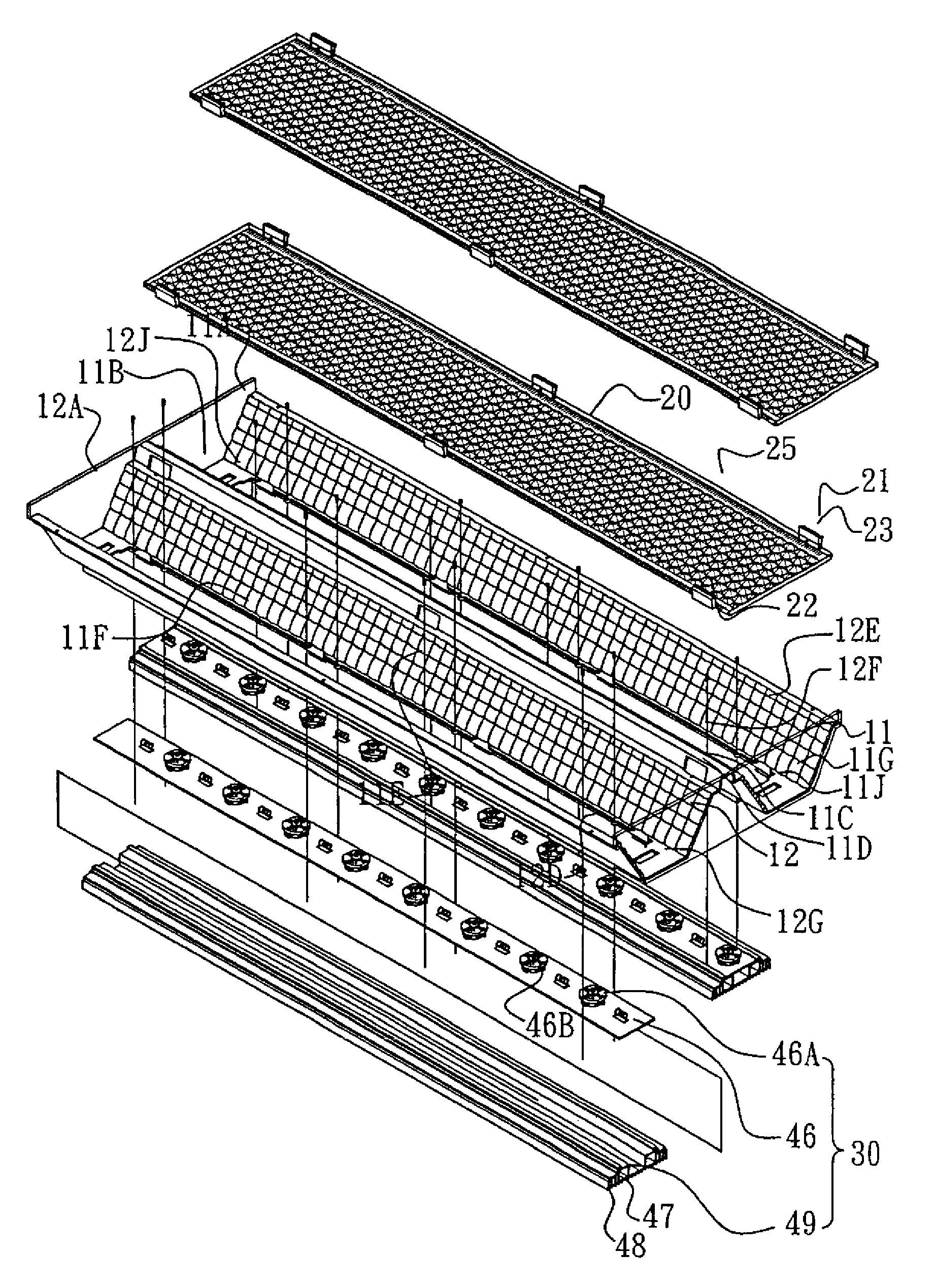
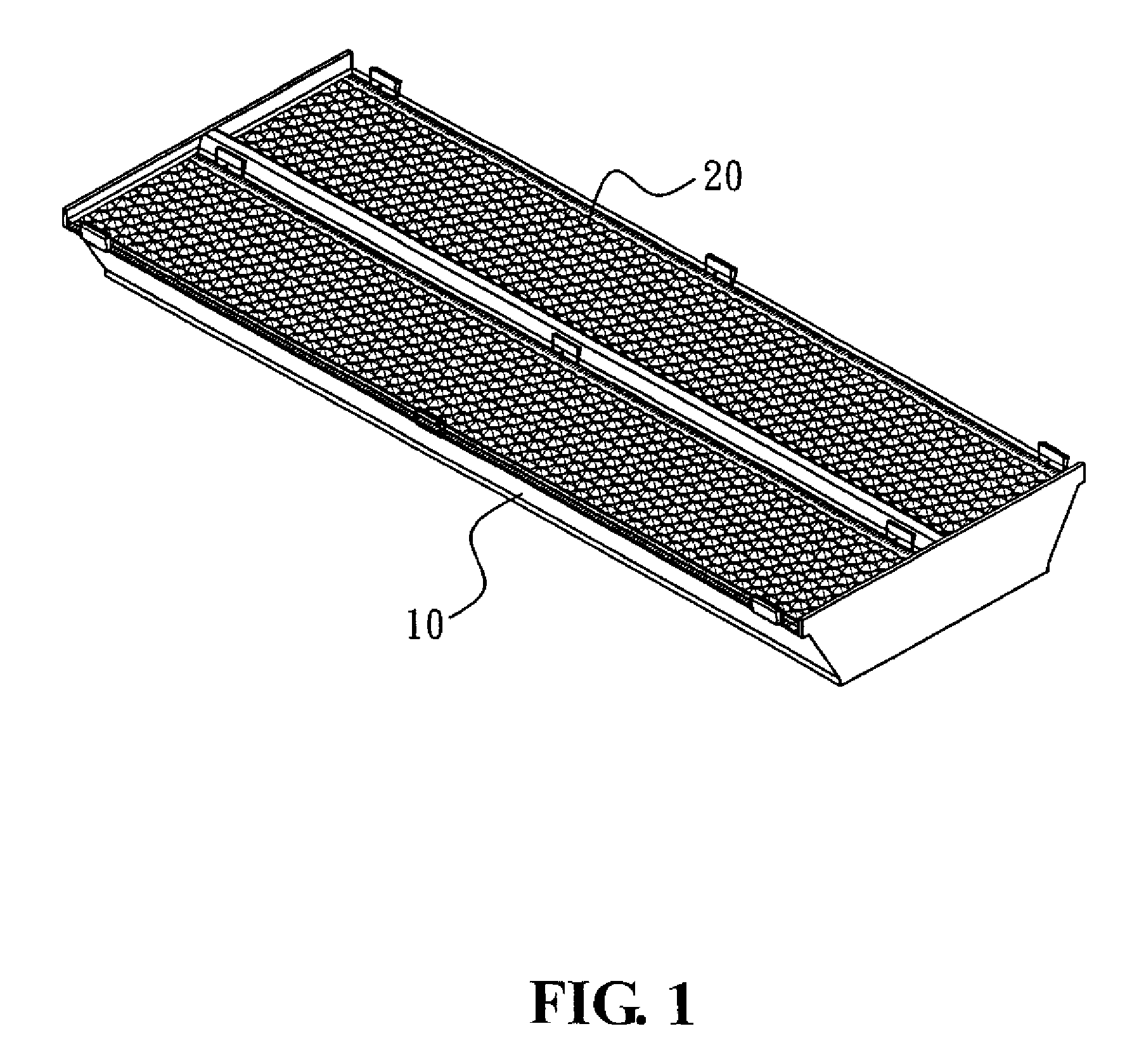
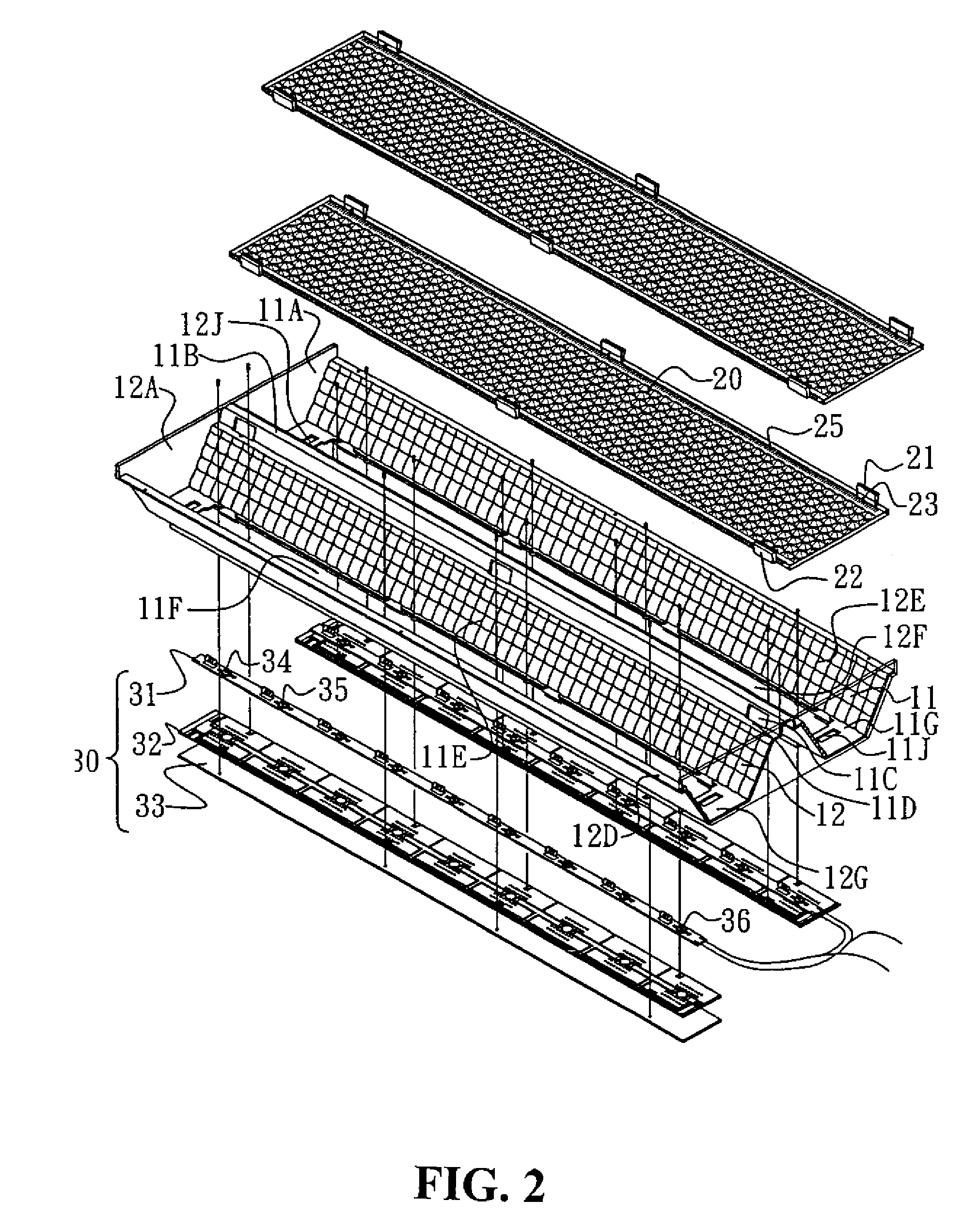
[0023]FIG. 1 shows a perspective view of a ceiling light fixture constructed in accordance with the present invention. The ceiling light fixture, as shown, has an exterior appearance that looks similar to one of the currently available ceiling light fixture. However, the ceiling light fixture of the present invention has a distinct interior structure, as particularly illustrated in FIG. 2, which shows an exploded view of the ceiling light fixture of the present invention, FIG. 3, which also shows...


PUM


Abstract

A ceiling light fixture includes a housing forming a channel having a trapezoidal cross section and a light-transmitting cover panel fixed in and covering the channel. The channel has a bottom wall forming a slot. A circumferential mounting frame is formed on a back of the bottom wall of the channel and barbs extend from the mounting frame. The bottom wall further forms a fitting hole. The ceiling light fixture selectively receives a first lamp assembly in the mounting frame and secures the lamp assembly with the barbs so that a light source of the lamp assembly is exposed through the slot for irradiating light or alternatively an end seat of a lamp tube is fit and retained in the fitting hole to set and fix the lamp tube in the slot to realize interchangeable use of the ceiling light fixture with different lamp assemblies.

Description

BACKGROUND OF THE INVENTION[0001](a) Technical Field of the Invention[0002]The present invention relates to a ceiling light fixture that is adaptable to various lamp assemblies without modification of structure thereof so that discarding an original but still workable light fixture in the course of replacing the traditional more power-consuming light sources with a newly-developed, less power-consuming light source is not necessary and the amount of waste caused by discarding the original light fixture is substantially reduced.[0003](b) Description of the Prior Art[0004]The world is now in the beginning of the twenty-first century and people are now more aware of the fragile and delicate balance between the amount of energy consumed and the global weather than those living in the years of industrial revolution and the modern realizes that the Earth will die and become hostile to life forms very soon due to depletion of resources and deterioration of ecological environment if low ene...

Claims


Application Information

Patent Timeline
Patent Type & Authority Patents(United States)
IPC IPC(8): F21S8/00F21S19/00F21S4/00F21V21/00
CPCF21S8/04F21V3/00F21V15/01F21V17/164F21V19/0015F21V19/003F21K9/00F21V19/0085F21Y2101/02F21Y2103/00F21K9/66F21Y2115/10
Inventor CHIANG, WEN-CHIANG
Owner VALENS
Why Eureka
Try Eureka