Drum

a drum and drum head technology, applied in the field of drums, can solve the problems of inability to produce a sharp drum sound, inability to last for a long time, and relatively high loss of vibration energy

Inactive Publication Date: 2010-04-06
YAMAHA CORP
View PDF12 Cites 15 Cited by
  • Summary
  • Abstract
  • Description
  • Claims
  • Application Information

AI Technical Summary

Benefits of technology

[0027]It is an object of the present invention to provide a drum whose tone color can be varied without changing the size and depth of a drum shell.
[0032]Since the tone color change member is attached to the air hole to produce a load to air flow, it is possible to appropriately change the tone color of a drum sound without substantially changing the depth of the drum shell.

Problems solved by technology

The second type of snare drum suffers from slow damping of vibration; hence, it cannot produce a sharp drum sound.
However, the vibration of the drumhead 3 cannot last stably, and loss of vibration energy is relatively high; hence, the vibration will be rapidly damped.
When air flow occurs from the outside to the inside via the air hole 11 of the drum shell 2, a rapid state transition occurs in a short time period with respect to the drumhead 3 from an unstable vibrating state to a stable vibrating state, offering a small energy loss (in which the drumhead 3 vibrates about the normal position thereof), wherein the vibration of the drumhead 3 is damped slowly; hence, it is difficult to produce an adequately sharp drum sound.
Hence, it is very troublesome in designing the check valve; this increases the number of check valves for use in different types of drums.
The check value is provided outside of the drum shell; hence, it greatly degrades the exterior appearance of a drum.
Similar to the drum of Patent Document 1, this drum is disadvantageous in that the slide mechanism, which is exposed outside of the drum shell, greatly degrades the exterior appearance thereof.
In particular, the depth of a drum shell greatly affects performance of a drum; hence, it is inconvenient for the user to experience unexpected variations of the depth of a drum shell.
In the foregoing drum in which a screen offering a damping effect or a screen for varying tone color is attached to the intermediate shell, it is very difficult to stably maintain the prescribed shape when the screen does not have a satisfactory degree of hardness; hence, there is a restriction in selecting materials for use in the screen.
But it is not suited to other drums whose drum shells have relatively small depths, such as snare drums, whose drum shells generally have depths of about 5.5 inches.
Similar to the drum of Patent Document 2, the drum of Patent Document 3 is disadvantageous in that the depth of the drum shell thereof gradually varies.
The drum of Patent Document 4 suffers from drawbacks in custody, maintenance, and transportation because various types of shell members having different materials and structures must be provided therefor.

Method used


Image

  • Drum
  • Drum
  • Drum

Examples


first embodiment

1. First Embodiment

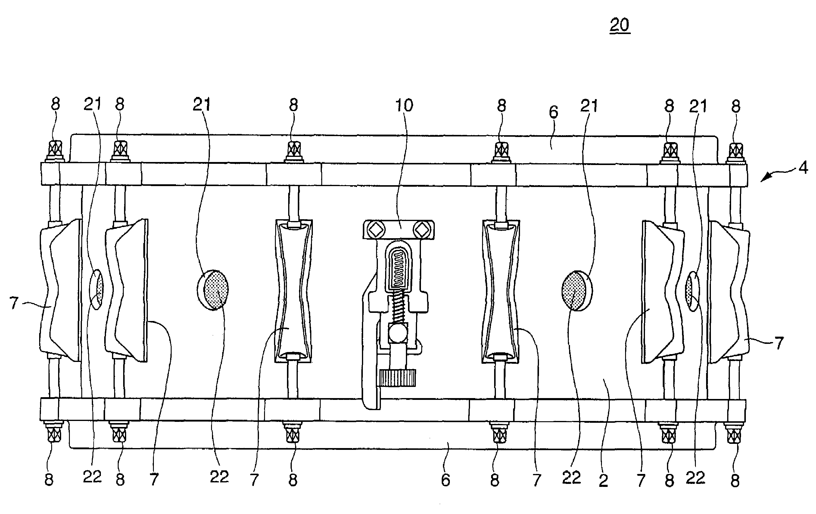
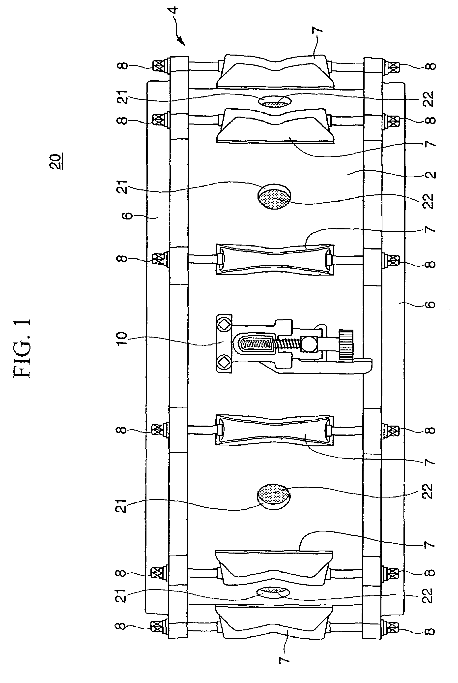
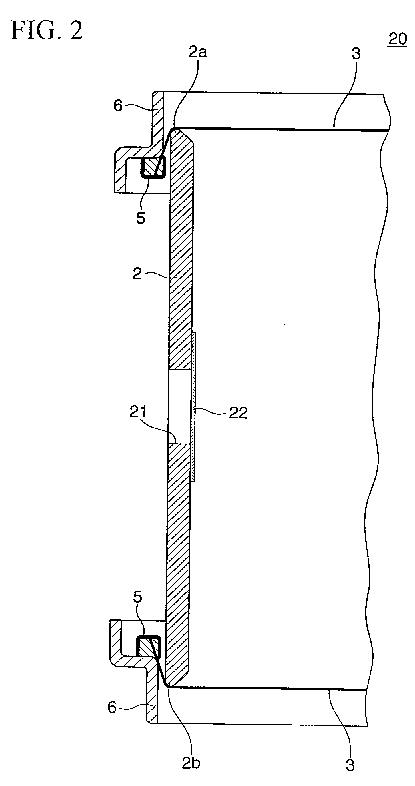
[0044]FIG. 1 is a front view of a snare drum 20 in accordance with a first embodiment of the present invention, and FIG. 2 is an enlarged cross-sectional view showing essential parts of the snare drum 20, wherein parts identical to those shown in FIG. 5 are designated by the same reference numerals.

[0045]The overall constitution of the snare drum 20 is basically identical to that of the snare drum 1 shown in FIG. 5 except that tone color change members 22 are fixed to air holes 21, which are formed at prescribed positions on the exterior surface of the drum shell 2 having a cylindrical shape and which establish communications between the inside and the outside of the drum shell 2. In the snare drum 20 of the first embodiment, the air holes 21 are formed in the circumferential direction of the drum shell 2 with prescribed distances therebetween. Of course, it is possible to modify the snare drum 20 to provide only a single air hole 21. It is possible to appropriate...

second embodiment

2. Second Embodiment

[0056]FIG. 3 is a front view showing the exterior appearance of a snare drum 30 in accordance with a second embodiment of the present invention. FIG. 4 is an enlarged cross-sectional view showing essential parts of the snare drum 30 shown in FIG. 3.

[0057]The snare drum 30 is formed using a drum shell 31 constituted of shells 31A and 31B, which are divided in an axial direction. The shells 31A and 31B are interconnected together by means of a plurality of lugs 7 (each composed of one piece) and strainers 10, which are attached across openings 33a (positioned opposite to openings 33b, across which the drumheads 3 are stretched), in such a way that their axial lines substantially match each other. Distal ends of each lug 7 are attached to the exterior surfaces of the shells 31A and 31B by means of bolts 34, which are screwed inwardly to run through the shells 31A and 31B at prescribed positions. The drumheads 3 are stretched under tension on the openings 33b positio...


PUM


Abstract

A drum is formed using a drum shell having openings at both ends thereof, across which drumheads are stretched under tension. At least one air hole is formed at a prescribed position of the exterior surface of the drum shell, allowing air flow to occur between the inside and the outside of the drum shell. At least one tone color change member, which is composed of cloth and rubber sheets, is attached to the interior wall of the drum shell in connection with the air hole; hence, the air hole is closed by the tone color change member. Thus, it is possible to appropriately change the tone color of drum sound without substantially changing the size of the drum, which can be designed similar to any types of conventionally known drums.

Description

BACKGROUND OF THE INVENTION[0001]1. Field of the Invention[0002]The present invention relates to drums such as bass drums, snare drums, and marching drums.[0003]The present application claims priority on Japanese Patent Application No. 2007-138995, the content of which is incorporated herein by reference.[0004]2. Description of the Related Art[0005]Drums such as bass drums, snare drums, and marching drums are each formed using a drum shell having a cylindrical shape having openings at both ends, across which drumheads are stretched under tension. When a drum is struck with a drumstick, primary sound is produced due to an impact between the drumstick and the drumhead. In a drum shell having opposite openings, across which first and second drumheads are stretched under tension, when the first drumhead is struck with a drumstick, vibration occurs by the first drumhead and is transmitted to the second drumhead by way of air inside of the internal hollow space of the drum shell, whereby ...

Claims


Application Information

Patent Timeline
Patent Type & Authority Patents(United States)
IPC IPC(8): G10D13/02G10D13/20G10D13/22
CPCG10D13/028G10D13/021G10D13/02G10D13/22G10D13/25G10D13/20
Inventor ABE, BANRI
Owner YAMAHA CORP
Why Eureka
Try Eureka