AI technical title is built by Patsnap AI team. It summarizes the technical point description of the patent document.
a technology of tooth and splint, which is applied in the direction of soil shifting machine/dredger, mechanical machine/dredger, construction, etc., can solve the problems of tooth function severely degraded, difficulty in absorbing, and normal blockage of the minimum aperture of the tensioning devi
Active Publication Date: 2010-04-13
COMBI WEAR PARTS AB +1
View PDF23 Cites 23 Cited by
Summary
Abstract
Description
Claims
Application Information
AI Technical Summary
This helps you quickly interpret patents by identifying the three key elements:
Problems solved by technology
Method used
Benefits of technology
Benefits of technology
[0026]An important object of the present invention is to achieve a new and improved tooth system for the tool for an earth removal machine, which tooth system essentially reduces or wholly eliminates the wear between the different connection parts caused by hammering and / or caused by too large surface loads on the tooth system's joint between the holder and tooth point.
[0027]Another object of the present invention is to achieve a new and improved tooth system, which tooth system essentially reduces or wholly eliminates the problem with disadvantageously large wear damage along the joint between the tooth system's component connection parts due to the very large loads arising during, e.g., the breaking of hard rock mass.
[0028]Yet another object of the present invention is to achieve a leg-type tooth system, which is easy to clean of dirt and earth removal residue that accumulate between the holder and the tooth portion and along the joint's contact and clearing surface(s), and further with a holder that can be easily repaired at its back side.
Problems solved by technology
The tooth systems according to U.S. Pat. No. 4,642,920 and DE-2 153 964 have several unsolved problems and disadvantages of which the following can be named:a disadvantageous leverage ratio for transverse (Fp) and normal (Fs) forces, which is substantially greater than one, why the tooth can bend or break off during hard work;that the tooth systems have difficulty absorbing the loads and torsional forces impacting at the front side of the holder, that is, at the forward joint surfaces in the cross-vertical plane (XZ), due to insufficient contact surfaces; for example, the torsional forces along said Y axis cause the corners of the substantially quadratic leg, as stipulated in DE-2 153 964 and U.S. Pat. No. 4,642,920, are quickly worn down after which the tooth's function is severely degraded since the tooth's position become rotated;and, further, the rear minimal aperture for the tensioning device is normally blocked by the same, which is why dirt fastens between tooth and holder, which dirt can only be removed with difficulty after the tooth system has been disassembled.
Here instead a complicated solution in the form of an elastic strap was used, that could be easily damaged or fall off when replacing a tooth when the midsection of the strap is arranged outside the holder.
Further the locking function is reduced or ceases altogether as the elastic strap is worn, ages, dries out and cracks or otherwise sustains damage.
It is also noted that if one or both of the ends of the straps would get caught in an inclined position in side the holder's cavity then the tooth leg can not be correctly inserted.
Method used
Image
Click on the blue label to locate the original text in one second.
Reading with bidirectional positioning of images and text.
Examples
Embodiment Construction
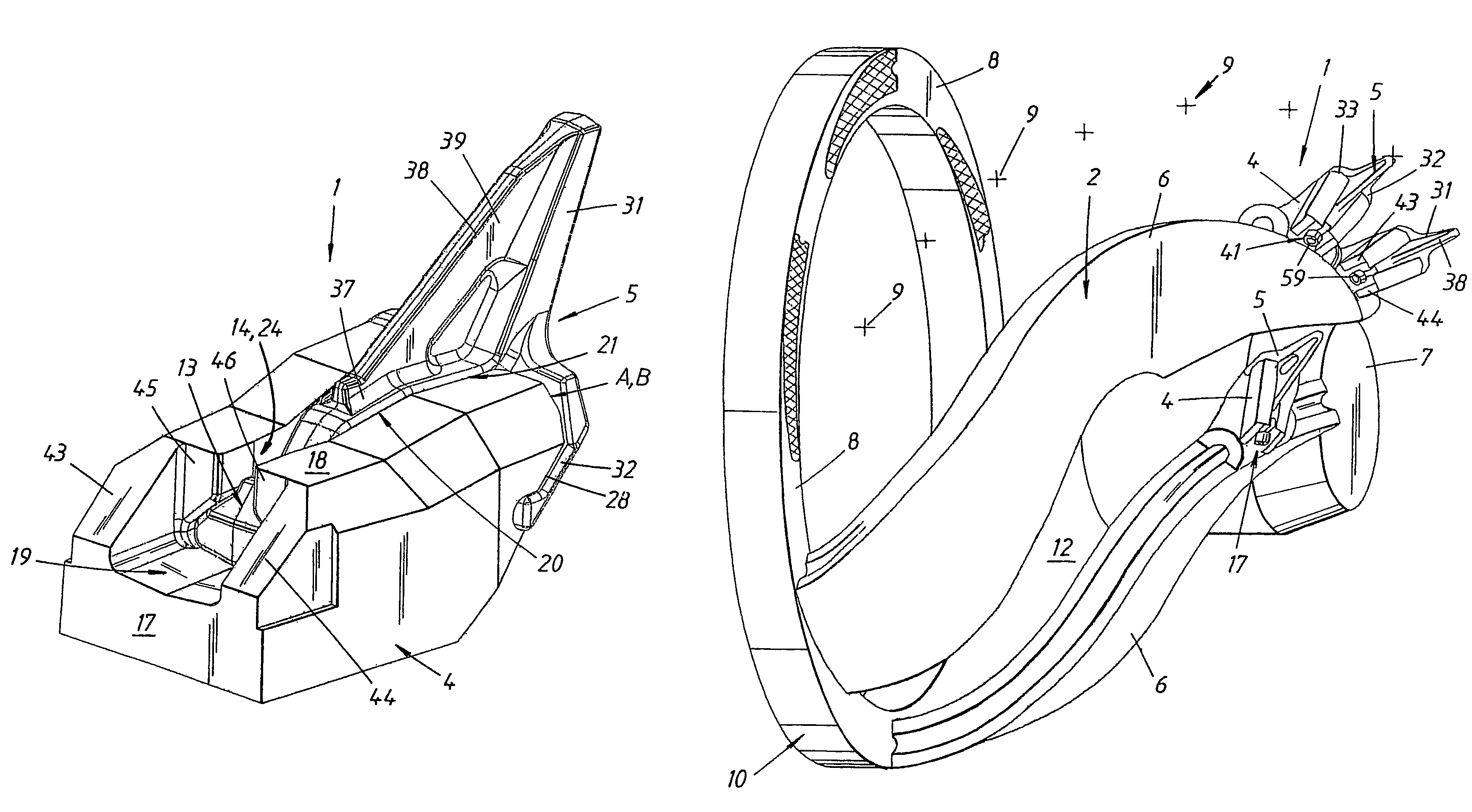
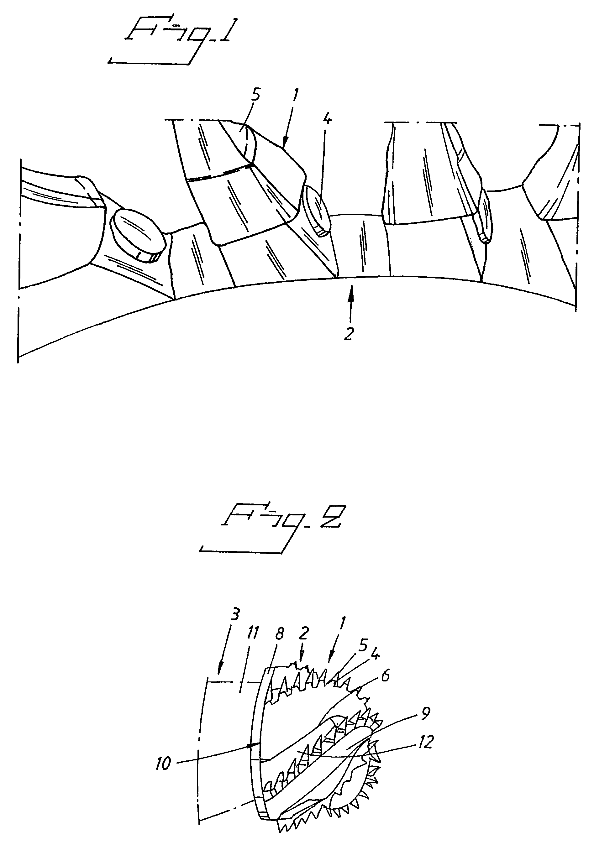
[0072]With reference to FIGS. 1 and 2, there is schematically shown a tooth system 1 intended for a tool 2 for an earth moving machine 3 for the loosening and breaking of more or less hard earth and rock mass from a working surface (W), see FIG. 17, whereupon these masses can be removed in a suitable manner. The present invention 1 is of the type that comprises a holder 4 arranged at the tool 2 and a frontal tooth portion 5 in the form of a replaceable wear and / or replacement part intended for the earth moving itself, which tooth portion 5 is removeably arranged in relation to and at the holder 4. The tooth system 2, thus, comprises two main connection parts in the form of a “female part”4 and a “male part”5 that together form a unified and assembled “tooth”. The holder 4 forms, preferably though not necessarily, the female part 4 of the present invention.
[0073]Examples of an earth moving machine 3, tool 2 and wear and / or replacement parts 5 suitable for a tooth system 1 in accordan...
PUM
Abstract
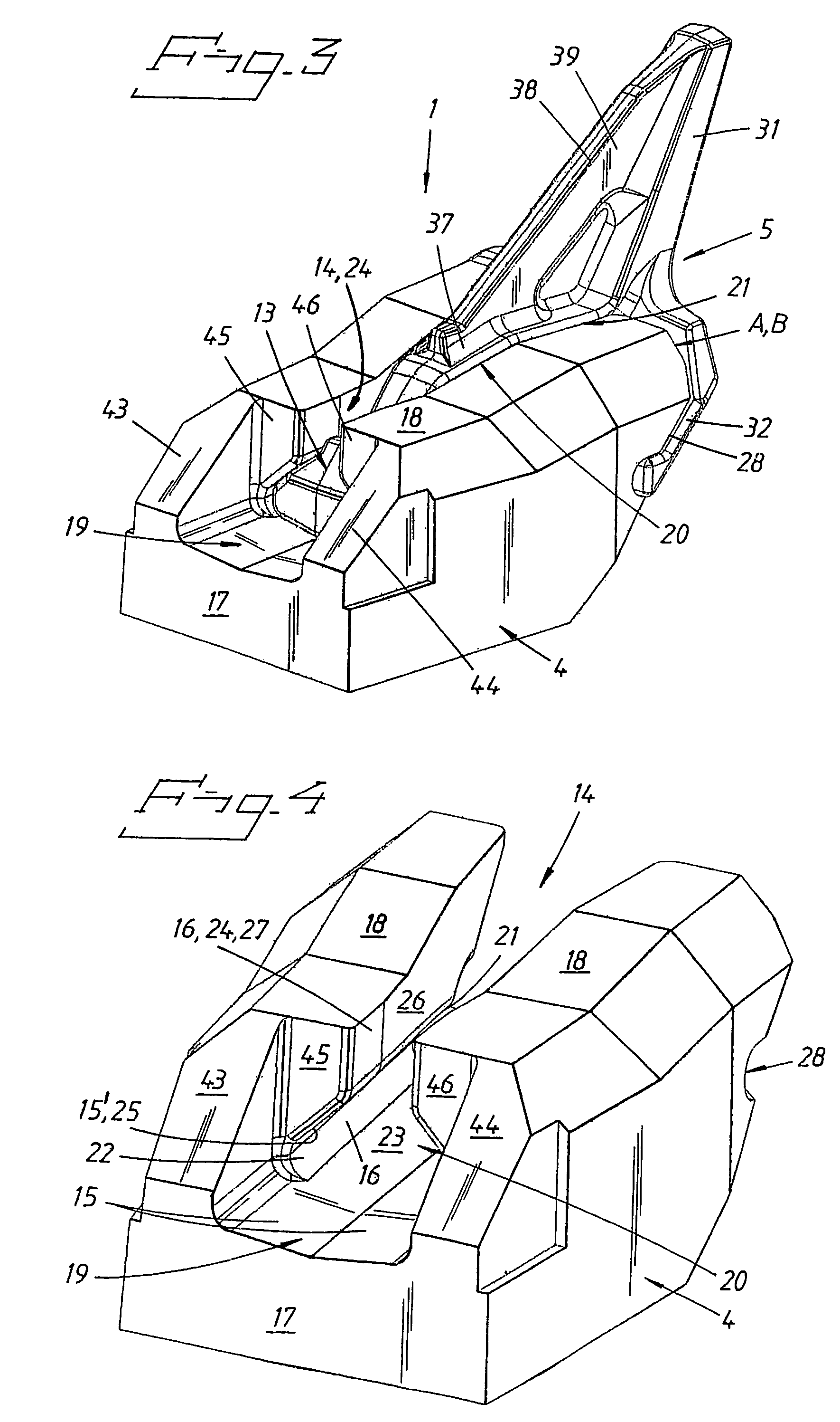
A tooth system (1) for a tool (2) for earth moving machinery (3) is disclosed, which tooth system is of the type embodying a holder (4) located on the tool and a front tooth portion (5) that is detachably arranged on and in relation to the holder, which tooth portion is in the form of a replaceable wear and / or replacement part designed for the actual earth moving (W) and embodies a rear leg and the holder embodies a cavity (14) designed to receive the leg in interaction with the tooth portion and thereby achieve a unified joint (A, B, C, D) for assimilation of occurring loads (Fs, Fc, Fp) via a predetermined connection geometry embodying special, opposite, mutually interacting contact surfaces (15) and, at least initially, clearance surfaces (16) that are arranged along the tooth portion and holder. Thus, in accordance with the present invention one has achieved an improved tooth system distinguished by the tooth leg and holder cavity, along at least a front part of said joint (A, B, C, D), to have a multi-armed, preferably cruciform, cross section comprising at least four projection arms (31, 32, 33, 34) and at least four grooves (24, 28, 29, 30) each that interact with each projecting arm, respectively, which projection arms comprise an, essentially, vertically arranged, upper arm (31), an, essentially vertically arranged, lower heel (34) and two, essentially horizontally and laterally arranged, wing portions (32, 33), wherein a tensioning device (41) is arranged in the rear part (19) of the cavity in order to achieve adjustable tensioning that tightens the tooth portion in relation to the holder, essentially axially along the axial symmetry axis Y of the cavity.
Description
TECHNICAL AREA[0001]The present invention relates to a tooth system for a tool for earth moving machinery, which tooth system is of the type comprising a holder located on the tool and a front tooth portion that is detachably arranged on and in relation to the holder, which tooth portion is in the form of an exchangeable wear and / or replacement part intended for the actual earth moving, which tooth portion comprises a rear leg and the holder comprises a cavity designed to receive the leg in interaction with the tooth portion and thereby achieve a unified joint for assimilation of occurings loads, Fs, Fc, Fp, via a pre-determined connection geometry comprising special, opposite, mutually interacting contact surfaces and, at least initially, clearance surfaces that are arranged along the tooth portion and holder.PROBLEM PRESENTATION AND BACKGROUND TO THE INVENTION[0002]Today there are a number of different commercial tooth systems for replaceable wear and / or replacement parts for tool...
Claims
Application Information
Patent Timeline
Application Date:The date an application was filed.
Publication Date:The date a patent or application was officially published.
First Publication Date:The earliest publication date of a patent with the same application number.
Issue Date:Publication date of the patent grant document.
PCT Entry Date:The Entry date of PCT National Phase.
Estimated Expiry Date:The statutory expiry date of a patent right according to the Patent Law, and it is the longest term of protection that the patent right can achieve without the termination of the patent right due to other reasons(Term extension factor has been taken into account ).
Invalid Date:Actual expiry date is based on effective date or publication date of legal transaction data of invalid patent.

