Air induction housing having a perforated wall and interfacing sound attenuation chamber

a technology of air induction housing and interfacing sound attenuation chamber, which is applied in the direction of machine/engine, combustion-air/fuel-air treatment, charge feed system, etc., can solve the problems of increasing installation complexity, packaging volume accommodation, and generating noise (i.e., unwanted sound), and achieve the highest level of intake noise attenuation, minimize the audibility of intake noise, and large airflow

Inactive Publication Date: 2010-04-13
GM GLOBAL TECH OPERATIONS LLC
View PDF12 Cites 15 Cited by
  • Summary
  • Abstract
  • Description
  • Claims
  • Application Information

AI Technical Summary

Benefits of technology

[0010]The size, number and arrangement of the perforations and the dimensional aspects of the sound attenuation chamber are selected, per the configuration of the air induction housing and the airflow requirements of the internal combustion engine, such that a multi-faceted synergy is achieved whereby: 1) ample airflow is provided through the perforations and superposed tubes to supply the internal combustion engine with required aspiration over a predetermined range of engine operation, and 2) audibility of intake noise is minimized. The multi-faceted synergy is based upon simultaneous optimization of four facets: 1) providing a plurality of perforations which collectively have an area that accommodates all anticipated airflow (aspiration) requirements of a selected internal combustion engine; 2) minimizing the diameter while simultaneously adjusting the area of the perforations such that the airflow demand of the internal combustion engine involves an airflow speed through each perforation that is below a predetermined threshold at which the perforation airflow noise generated by the flow of the air through the perforations is acceptably inaudible; 3) arranging the perforation distribution in cooperation with configuring of the air induction housing to provide a highest level of intake noise attenuation thereat (i.e., minimal audibility); and 4) further attenuating intake noise at a sound attenuation chamber by a plurality of apertures in the sidewalls of the tubes providing a Helmholtz resonator.
[0012]Accordingly, it is an object of the present invention to provide an air induction housing having a perforated wall which provides a first intake noise attenuation modality and having a sound attenuation chamber interfaced with the perforated wall which provides a second intake noise attenuation modality, wherein multiply apertured tubes thereof are superposed the wall perforations so that, attendant to the noise attenuation, ample air entry into the air induction housing is provided.

Problems solved by technology

Problematically, a consequence of the combustion of the fuel-air mixture within the internal combustion engine is the generation of noise (i.e., unwanted sound).
A component of this noise is intake noise which travels through the intake manifold, into the air induction housing, and then radiates out from the at least one air induction opening.
The intake noise varies in amplitude across a wide frequency spectrum dependent upon the operational characteristics of the internal combustion engine, and to the extent that it is audible to passengers of the motor vehicle, it is undesirable.
While the prior art solution to provide attenuation of intake noise does work, it does so by requiring the inclusion of an externally disposed snorkel and resonator combination which adds expense, installation complexity and packaging volume accommodation.

Method used


Image

  • Air induction housing having a perforated wall and interfacing sound attenuation chamber
  • Air induction housing having a perforated wall and interfacing sound attenuation chamber
  • Air induction housing having a perforated wall and interfacing sound attenuation chamber

Examples


Embodiment Construction

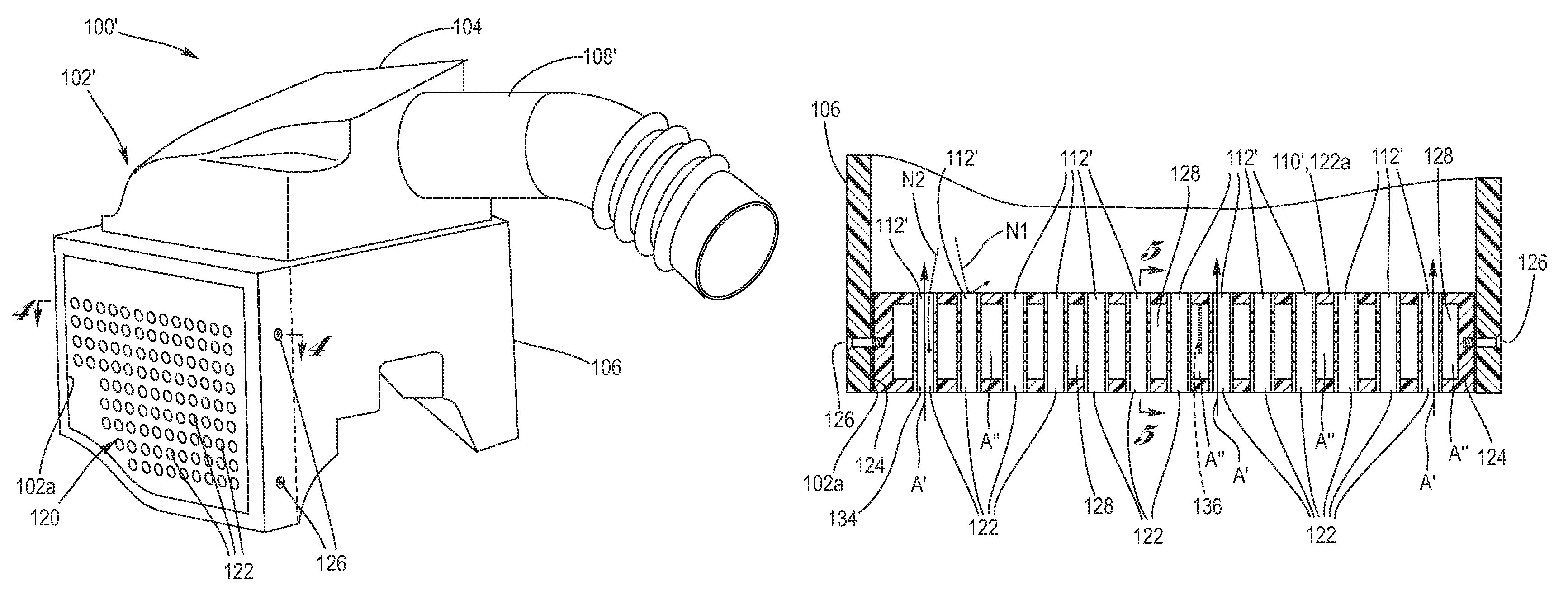
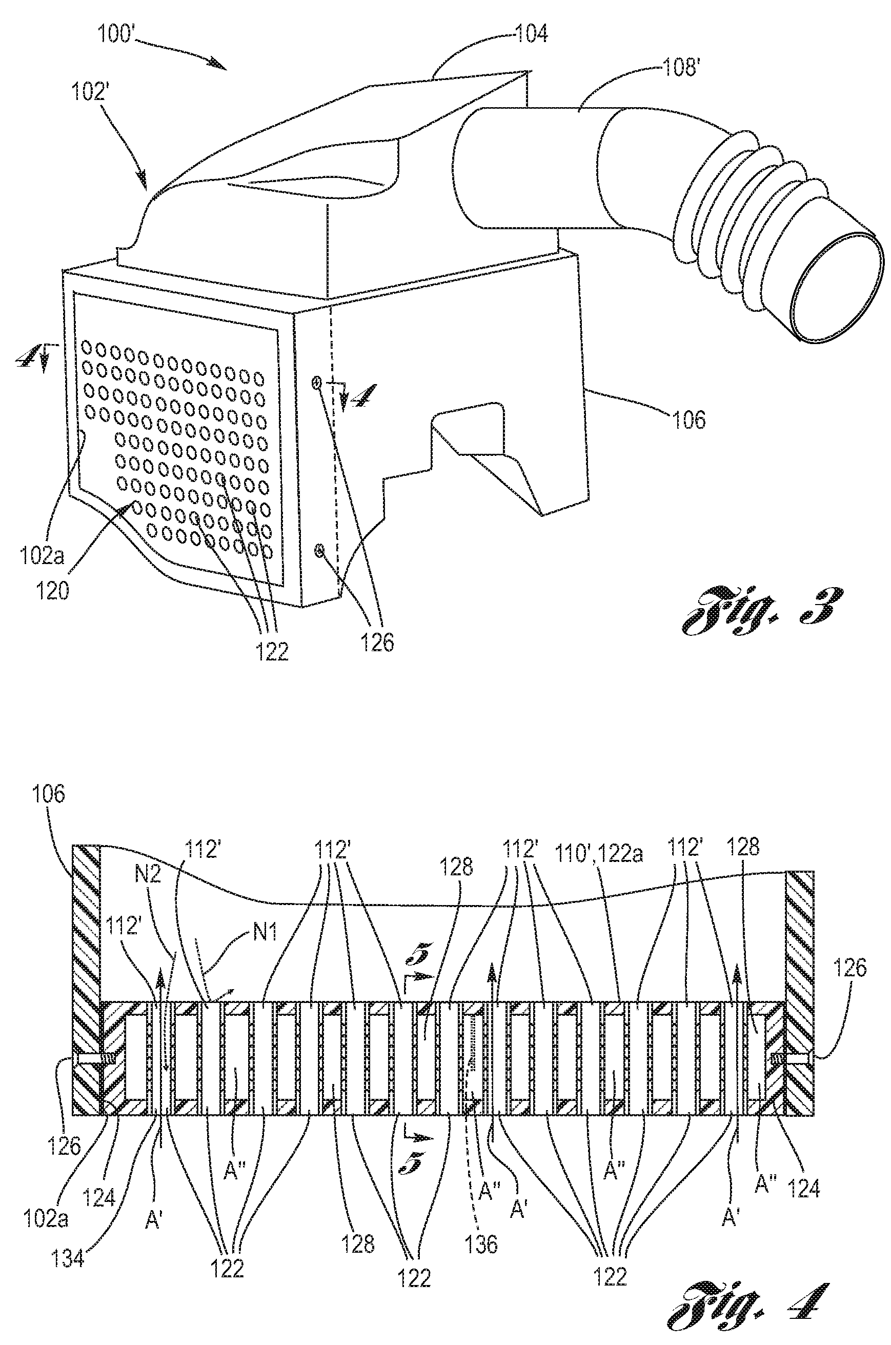
[0025]Referring now to the Drawing, FIGS. 2A through 10 depict various aspects of an air induction housing having a perforated sound attenuation wall and interfacing sound attenuation chamber according to the present invention.

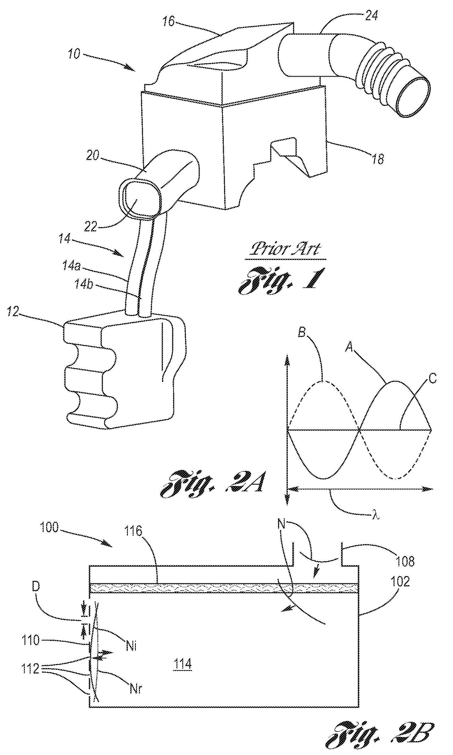
[0026]FIGS. 2A and 2B show principles of physics under which it is believed an air induction housing having a perforated sound attenuation wall according to the present invention provides acoustic (sound) attenuation of intake noise, without resort to an external snorkel and resonator combination as used in the prior art.

[0027]FIG. 2A demonstrates the principle of destructive interference of acoustic (sound) waves. In this case, acoustic wave A is 180 degrees out of phase with acoustic wave B. As a result, if acoustic waves A and B have the same amplitude, then they completely cancel one another by destructive interference, the result being line C of zero amplitude.

[0028]Turning attention next to FIG. 2B, a schematic representation of air induction housing hav...


PUM


Abstract

An air induction housing having a perforated wall which provides a first intake noise attenuation modality and further having a sound attenuation chamber interfaced with the perforated wall which provides a second intake noise attenuation modality. Multiply apertured tubes of the sound attenuation chamber provide a Helmholtz resonator, wherein the tubes are superposed the wall perforations so that, attendant to the noise attenuation, ample air entry into the air induction housing is provided. The size, number and arrangement of the perforations is selected such that ample airflow is provided and audibility of intake noise is minimized in conjunction with the corresponding tubes of the sound attenuation chamber.

Description

TECHNICAL FIELD[0001]The present invention relates to air induction housings used in the automotive arts for air intake and air filtration for supplying intake air to an internal combustion engine. More particularly, the present invention relates to an air induction housing having a perforated wall for simultaneously providing air intake and sound (acoustic) attenuation, and still more particularly, to a sound attenuation chamber having multiply apertured tubes superposed the perforations.BACKGROUND OF THE INVENTION[0002]Internal combustion engines rely upon an ample source of clean air for proper combustion therewithin of the oxygen in the air mixed with a supplied fuel. In this regard, an air induction housing is provided which is connected with the intake manifold of the engine, wherein the air induction housing has at least one air induction opening for the drawing-in of air, and further has a filter disposed thereinside such that the drawn-in air must pass therethrough and ther...

Claims


Application Information

Patent Timeline
Patent Type & Authority Patents(United States)
IPC IPC(8): F02M35/10
CPCF02M35/1216F02M35/1244F02M35/1261
Inventor KOSS, JULIE A.
Owner GM GLOBAL TECH OPERATIONS LLC
Why Eureka
Try Eureka