Window shade with coil spring drive

a technology of coil springs and windows, applied in the direction of curtain suspension devices, passenger space, building components, etc., can solve the problem that the positive engagement of driving elements only requires an extremely low installation force in the axial direction, and achieves the effect of superior spring characteristics, spring drive, and easy installation

Inactive Publication Date: 2010-04-13
BOS
View PDF14 Cites 30 Cited by
  • Summary
  • Abstract
  • Description
  • Claims
  • Application Information

AI Technical Summary

Benefits of technology

[0007]In view of the foregoing, a general objection of the present invention is to provide a window shade arrangement for motor vehicles that has superior spring characteristics and allows the spring drive to be installed more easily.
[0010]Since tolerance issues can easily arise during the attachment of the shade element to the winding shaft, the positive driving elements are subject to a certain tolerance with respect to their angular position. The utilization of positive driving elements makes it possible to reduce the ultimate deviation to a minimum during the assembly by choosing the smallest angle of rotation of the winding shaft possible during the assembly. In addition, the positively engaged driving elements only require an extremely low installation force in the axial direction when the coil spring housing is installed on the winding shaft together with the coil spring.
[0016]In the assembled state, the coupling shaft cannot be axially displaced to such an extent that the connection with either the coil spring or the winding shaft is broken. However, the backward and forward movements of the winding shaft, under certain circumstances, may cause the coil spring, which is quite rigidly connected to the coupling shaft, to be pressed against a wall of the housing by the winding shaft and scrape thereon. This effect can be eliminated by supporting the coupling shaft in the coil spring housing such that the coupling shaft is separately secured in the axial direction. For this purpose, the coil spring can be provided with a peripheral annular groove, into which a tangentially extending bolt engages. This bolt can also be spring loaded in the radial direction relative to the coupling shaft such that the winding shaft is radially tensioned in one direction and any risk of rattling is eliminated. In addition, the spring loaded bolt allows an axial displacement of the coupling shaft in order to unlock a locking device, if so required.
[0017]The preassembly can be realized in a particularly simple fashion if the tensioning device consisting of the coil spring housing, the coil spring and the coupling shaft is provided with a locking device. This locking device serves for locking the spring in the wound up state. The locking of the spring can take place at the preassembly plant or location and prevents installation errors during the subsequent installation. This means that, during installation work, winding up the coil spring to the required tension is no longer necessary.

Problems solved by technology

Since tolerance issues can easily arise during the attachment of the shade element to the winding shaft, the positive driving elements are subject to a certain tolerance with respect to their angular position.
In addition, the positively engaged driving elements only require an extremely low installation force in the axial direction when the coil spring housing is installed on the winding shaft together with the coil spring.

Method used


Image

  • Window shade with coil spring drive
  • Window shade with coil spring drive
  • Window shade with coil spring drive

Examples


Embodiment Construction

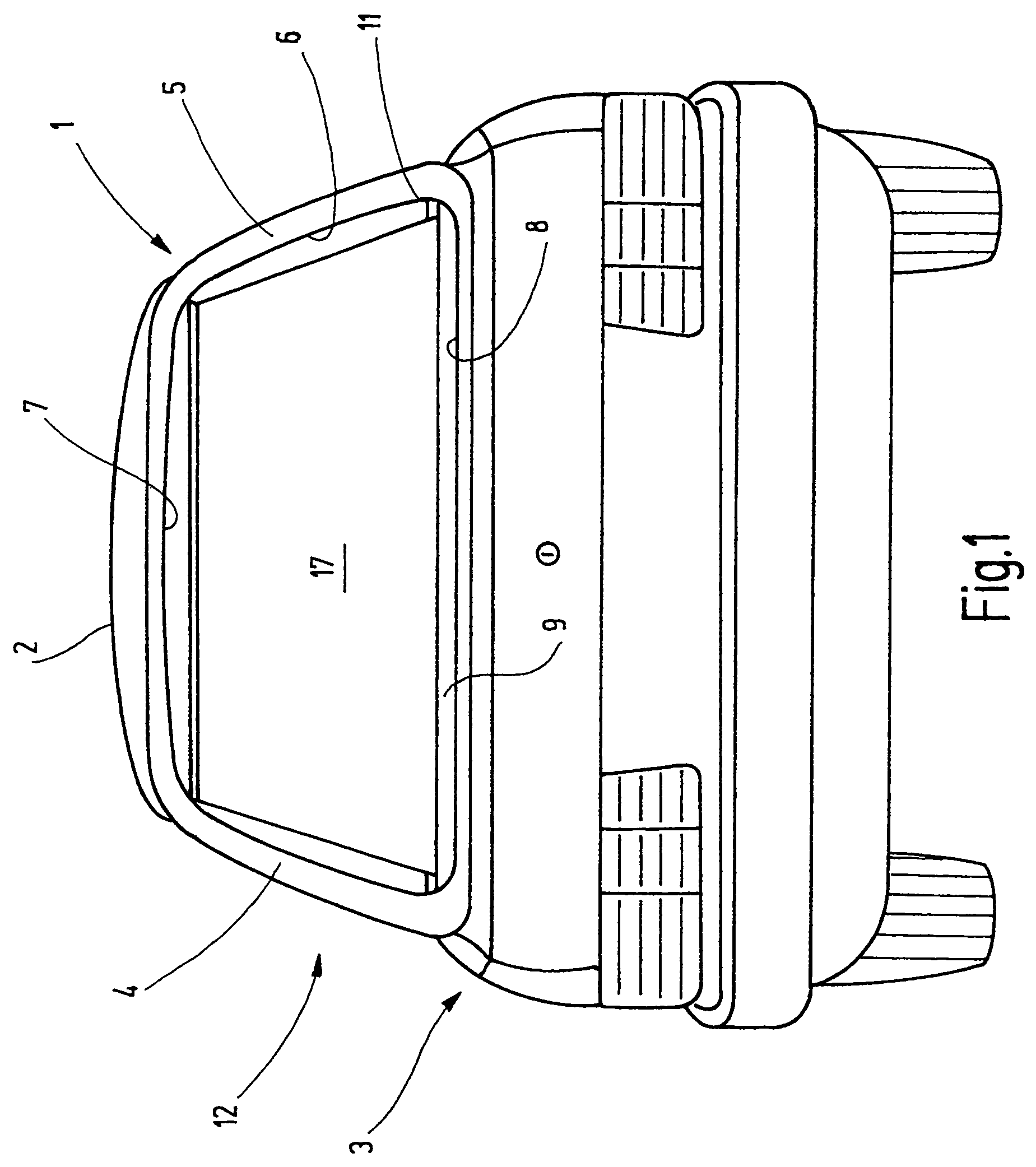
[0030]FIG. 1 provides a schematic rear view of a motor car 1 with a roof 2, a trunk 3 and two C columns 4 and 5. A rear window opening 6 is situated between the two C columns 4 and 5. The rear window opening 6 is limited by a rear roof edge on the upper side and by a window parapet 8 on the lower side. A rear window is conventionally mounted in the rear window opening 6.

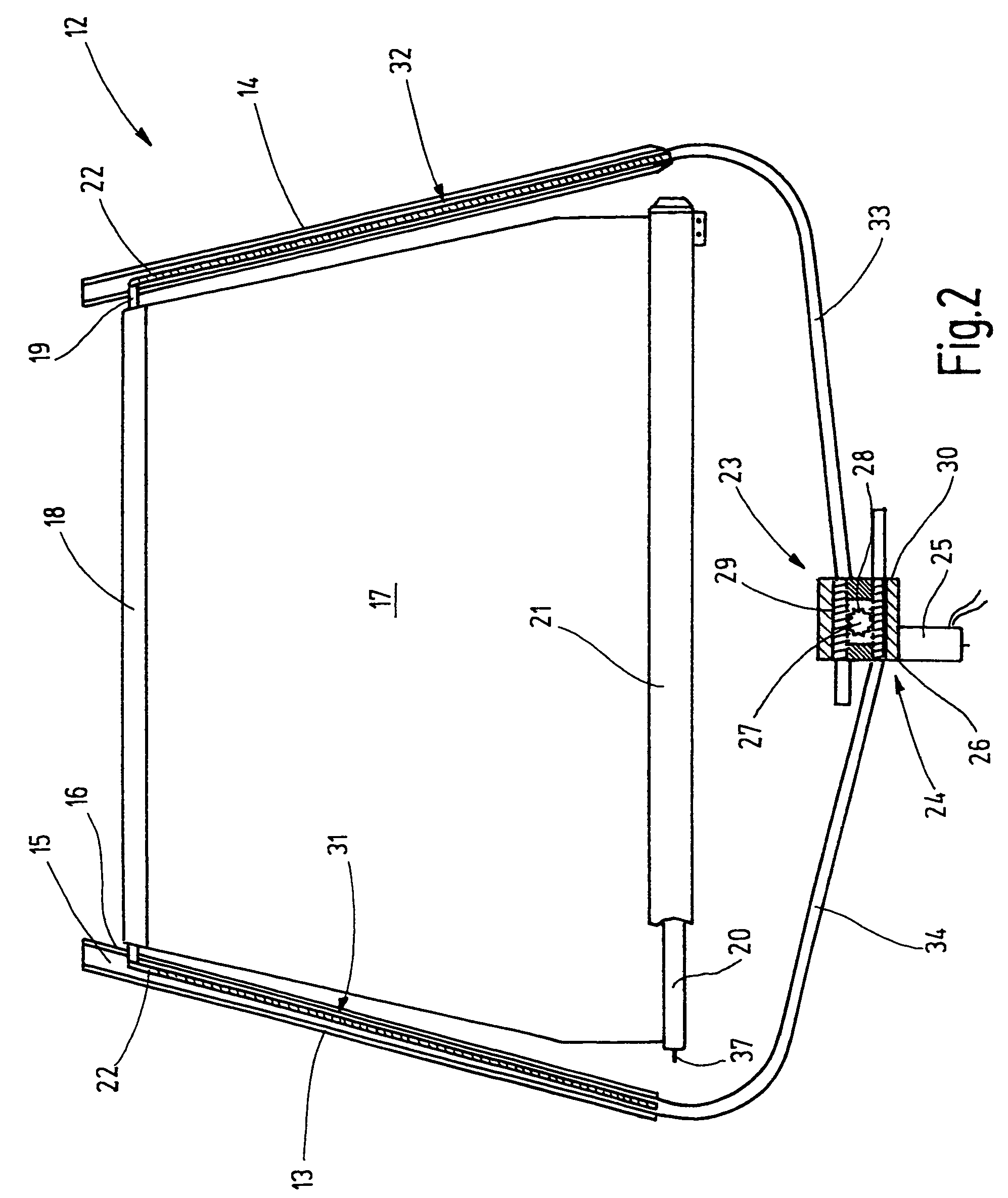
[0031]In the interior of the motor car 1, a rear window shelf 9 is situated underneath the rear window. The rear window shelf 9 extends horizontally between the lower window edge 8 and a rear seat back rest that is not shown in FIG. 1. The rear window shelf 9 has a straight extraction slot 11. The extraction slot 11 relates to a rear window shade 12 that is shown in FIG. 2.

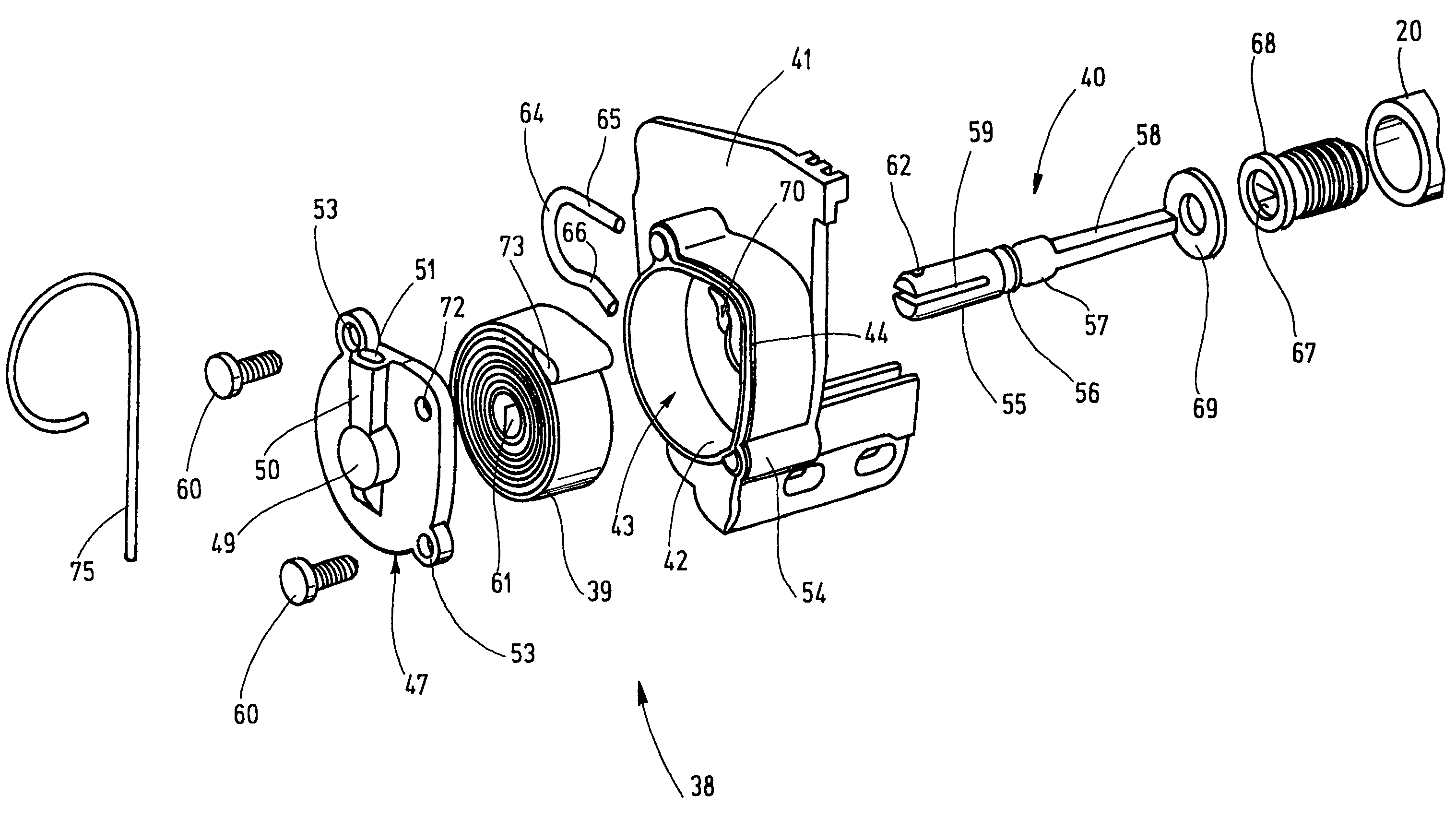
[0032]The rear window shade 12 includes two guide rails 13 and 14 that are sunk into the C columns 4 and 5 adjacent to the window edges. The guide rails respectively contain a guide groove 15 that opens in the direction of the respectively opposite...


PUM


Abstract

A window shade arrangement for a motor vehicle is provided that contains a housing in which a winding shaft is rotatably supported. A strip shaped shade element is fixed on the winding shaft. The cover of the window shade housing is formed by a spring housing. A coil spring for tensioning the winding shaft in the wind up direction of the strip shaped shade is seated in the spring housing. The spring housing, the spring seated therein and a coupling shaft form a preassembled unit.

Description

FIELD OF THE INVENTION[0001]The present invention relates to window shade arrangements for motor vehicles.BACKGROUND OF THE INVENTION[0002]In window shades that are commonly used in modern motor vehicles, a spring drive is used for tensioning the winding shaft of the window shade in the wind up direction of the strip shaped shade. The spring drive is formed by a helical spring that is accommodated in the interior of the winding shaft. This arrangement was predominantly utilized in the past because the winding shaft can be easily utilized as the housing for the spring drive due to its tubular shape. This was based on the notion that the spring drive can be accommodated in a space saving fashion at this location without creating major problems.[0003]The winding shaft needs to carry out approximately 10-15 revolutions between a fully extracted position of the strip shaped shade and a completely retracted position in which the strip shaped shade is largely wound up on the winding shaft....

Claims


Application Information

Patent Timeline
Patent Type & Authority Patents(United States)
IPC IPC(8): B60J3/00B60J1/20E06B9/60
CPCB60J1/2027B60J1/2033E06B9/60B60J1/208B60J1/2063B60J3/02
Inventor SCHIMKO, DANJAHANSEN, MELFTHURNAU, CHRISTIAN
Owner BOS
Why Eureka
Try Eureka