Electrically insulated conductor connection assemblies and associated method

a technology of electrical insulation and connection assemblies, applied in the direction of coupling contact members, coupling device connections, conductor screwing into other parts, etc., can solve the problems of difficult, if not impossible, to achieve the requisite level of electrical insulation, and to difficult unfasten (e.g., separate or disconnect) the individual components of the joint. , to achieve the effect of convenient unfastening

Active Publication Date: 2010-04-13
EATON INTELLIGENT POWER LTD
View PDF6 Cites 19 Cited by
  • Summary
  • Abstract
  • Description
  • Claims
  • Application Information

AI Technical Summary

Problems solved by technology

Specifically, the joints where electrical connections are made between components of the circuit breaker, such as between each terminal (e.g., line terminal; load terminal) and the corresponding electrical conductor (e.g., line conductor; load conductor) of the circuit breaker are one area where it is particularly difficult to achieve the requisite level of electrical insulation.
However, such an encapsulating approach disadvantageously makes it difficult, if not impossible, to unfasten (e.g., separate or disconnect) the individual components of the joint once it has been assembled and encapsulated.

Method used


Image

  • Electrically insulated conductor connection assemblies and associated method
  • Electrically insulated conductor connection assemblies and associated method
  • Electrically insulated conductor connection assemblies and associated method

Examples


example 1

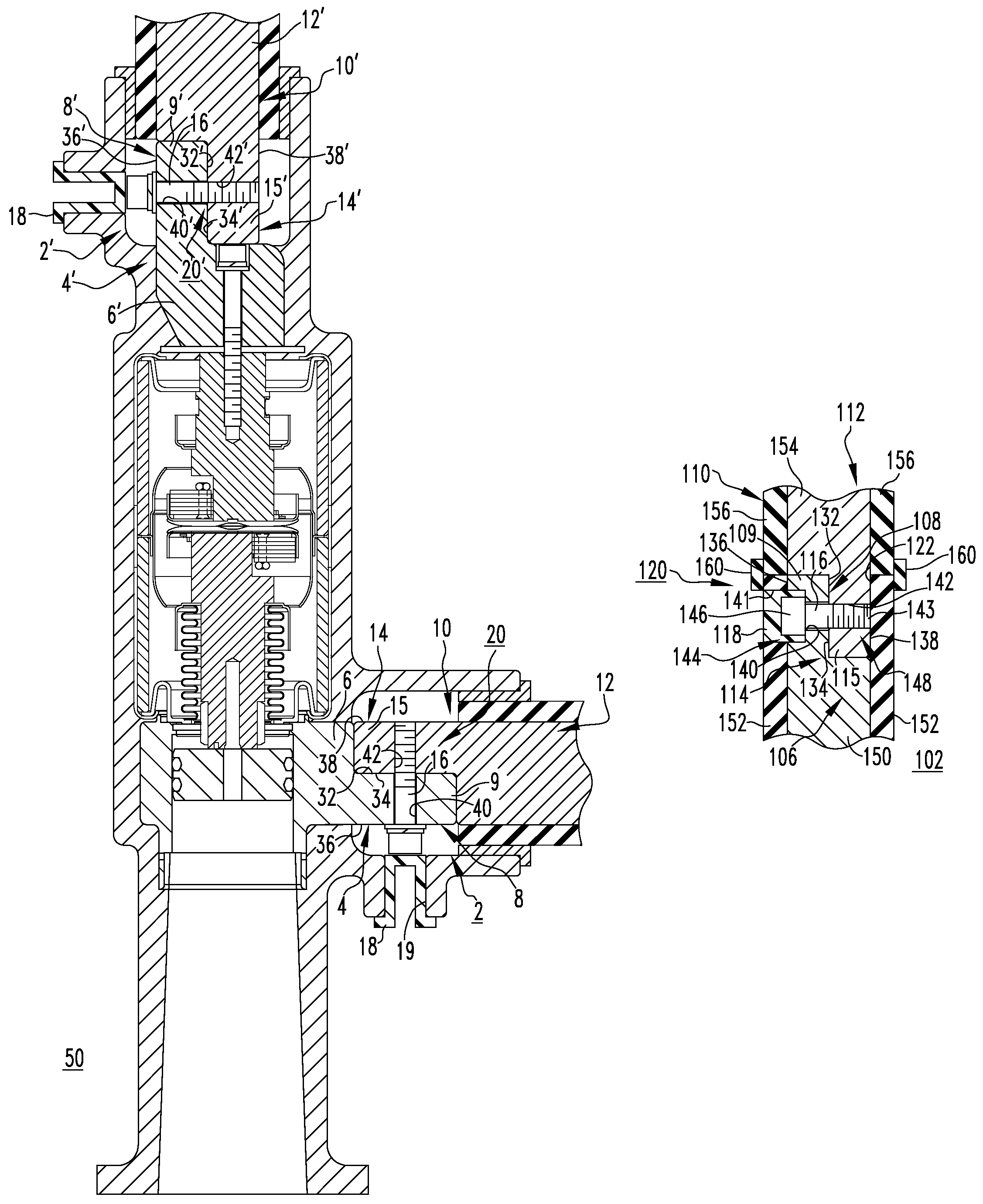
[0031]FIG. 1 shows two conductor connection assemblies 2,2′ for an electrical switching apparatus, such as the power circuit breaker 50 which is partially shown. It will, therefore, be appreciated that in the example of FIG. 1, the conductor connection assemblies comprise a load conductor connection assembly 2 and a line conductor connection assembly 2′. The load conductor connection assembly 2 includes a first electrical conductor 4 having a body portion 6 and an end portion 8, and a second electrical conductor 10 having a body portion 12 (partially shown) and an end portion 14. The first electrical conductor 4 of the example load conductor connection assembly 2 is the load terminal 4 of the power circuit breaker 50, and the second electrical conductor 10 is a corresponding load conductor 10 (e.g., without limitation, load bus; electrical cable; electrical wire) which is structured to be electrically connected to the load terminal 4 by a fastening mechanism such as, for example and...

example 2

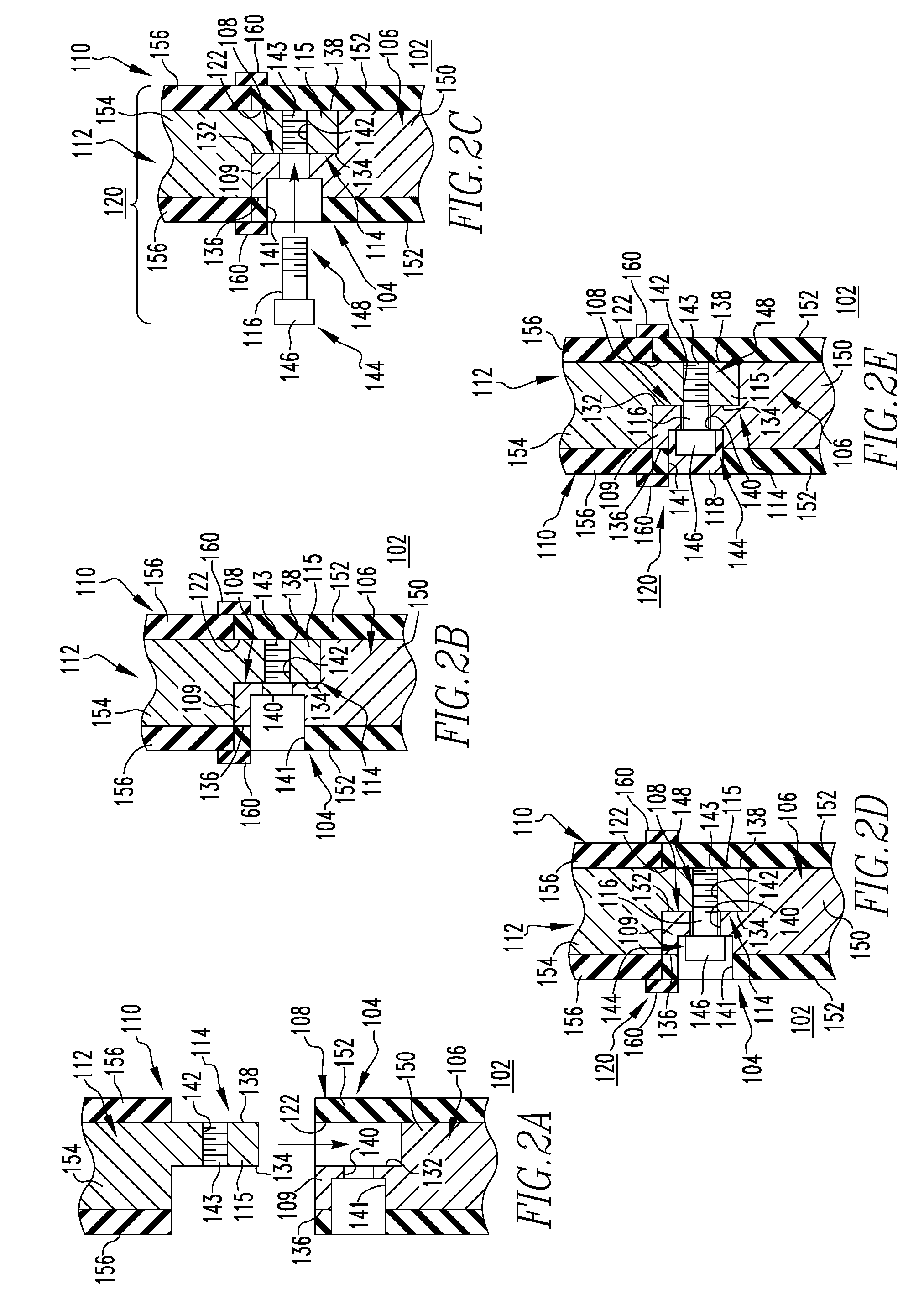
[0036]FIGS. 2A-2E show a conductor connection assembly 102, and the sequential steps of forming and electrically insulating the same. The first and second electrical conductors 104,110 of the conductor connection assembly 102 are substantially similar to electrical conductors 4,10 previously discussed in connection with FIG. 1, but the first electrical conductor 104 further includes a receptacle 122. The receptacle 122 is structured to receive protrusion 115 of the end portion 114 of the second electrical conductor 110, as shown in FIGS. 2B-2E. Similar to conductor connection assembly 2 of FIG. 1, when the joint 120 (FIGS. 2C-2E) of conductor connection assembly 102 is fastened (FIGS. 2D and 2E), the first and second protrusions 109,115 of the end portions 108,114 of the first and second electrical conductors 104,110, respectively, overlap one another in order that the first and second apertures 140,142 of the end portions 108,114, respectively, align with respect to one another to ...

example 3

[0040]FIGS. 3A-3C show a conductor connection assembly 202 in which the first electrical conductor 204 comprises an insulated tubular covering 224 and a first round conductor 226 including a plurality of resilient fingers 227 surrounding a receptacle 222. The receptacle 222 is structured to receive a corresponding second round conductor 230 of the second electrical conductor 210, as shown in FIGS. 3B and 3C. Specifically, the resilient fingers 227 bias against the second round conductor 230 of second electrical conductor 210 in order to retain the second round conductor 230 within the receptacle 222.

[0041]The second electrical conductor 210 also includes an insulated tubular covering 228, which as best shown in FIG. 3A, is spaced from the second round conductor 230 at or about the end portion 214 of the second electrical conductor 210. Thus, when the joint 220 is fastened, the second round conductor 230 is disposed within the resilient fingers 227 of the first electrical conductor 2...


PUM

PropertyMeasurementUnit
conductor connectionaaaaaaaaaa
electricallyaaaaaaaaaa
electricalaaaaaaaaaa

Abstract

An electrically insulated conductor connection assembly and a method for providing the same are provided. The electrically insulated conductor connection assembly includes first and second electrical conductors each comprising a body portion and an end portion. A fastening mechanism electrically and mechanically connects the end portions of the first electrical conductor to the end portion of the second electrical conductor, and an insulator overlays and electrically insulates the fastening mechanism. The end portions of the first and second electrical conductors and the fastening mechanism form a joint, which is structured to be fastenable and unfastenable. When the joint is fastened and the insulator is overlaying the fastening mechanism, the joint is electrically insulated.

Description

BACKGROUND OF THE INVENTION[0001]1. Field of the Invention[0002]The invention relates generally to electrical switching apparatus and, more particularly, to conductor connection assemblies for electrical switching apparatus such as, for example, circuit breakers. The invention also relates to methods for providing electrically insulated conductor connection assemblies.[0003]2. Background Information[0004]Electrical switching apparatus, such as circuit breakers, provide protection for electrical systems from electrical fault conditions such as, for example, current overloads, short circuits, abnormal level voltage conditions and other fault conditions. Typically, circuit breakers include an operating mechanism having a switching device structured to open electrical contact assemblies in order to interrupt the flow of current through the conductors of an electrical system in response to such fault conditions.[0005]For example, circuit breakers, such as power circuit breakers for syste...

Claims


Application Information

Patent Timeline
Patent Type & Authority Patents(United States)
IPC IPC(8): H01R13/15
CPCH01H9/02H01R11/01H01R13/53H01R4/70H01R4/34H01R4/56Y10T29/49194
Inventor LECCIA, BRAD R.LAMMERS, ADRIMARCHAND, FRANCOISSCHOTEN, PAULVAN DIJK, MARCELSCHOONENBERG, GERARDVAN THIEL, JOHANNES JOSEPHUS GERARDUS
Owner EATON INTELLIGENT POWER LTD
Why Eureka
Try Eureka