Limb dampeners

a technology of dampeners and limbs, applied in the direction of bows/crossbows, white arms/cold weapons, weapons, etc., can solve the problems that the ball at the end of the arm cannot reach the surface of the split limb, and achieve the effect of reducing sound, vibration, and hand shock perception

Inactive Publication Date: 2010-04-27
WRIGHT STUART D
View PDF14 Cites 28 Cited by
  • Summary
  • Abstract
  • Description
  • Claims
  • Application Information

AI Technical Summary

Benefits of technology

[0015]The object of the invention is to provide a vibration dampening device that can be deployed on both split limb bows as well as solid limb bows. One preferred embodiment that seems to work well needs only to have damper device rotated 90 degrees when attaching to the bow limb. It will be apparent to the reader skilled in the art that when mounting on a solid limb, the hemispherical contacts will be placed for maximum coverage on limb. Likewise, when mounting damper device on split limb, it will need to be rotated to achieve this maximum coverage on each side of limb. Through experiments with high speed photography it has been observed that the movable members of the Limbjax move very close to the same frequency. It was further observed that balls at end of arms could not reach the surface of the split limb because of the interference with the split limb mount. One preferred embodiment would incorporate four outboard movable members of the same length and longer than inventors prior art, with two shorter members, each placed 35 degrees between the longer members. This would allow the members to oscillate at different frequencies to further enhance the vibration dampening characteristics of the device. This new invention has been observed to be superior to inventors prior art, especially for split limb bows as the problems of a large gap between limbs and the interference of the split limb mount is now negated. The invention discloses a vibration damper which is molded as a single piece of a soft, flexible elastomeric polymer with a central hub and through hole to accept a mount for placing said damper on either solid limb or split limb bows. The invention further discloses a vibration damper that when mounted to either solid limb or split limb bows by means of a mechanism described herein would greatly reduce sound, vibration, and perceived hand shock when an arrow is released from an archery bow. The device is also constructed from a thermoplastic elastomer compound with a hardness range between 30 Shore OO to 13 Shore A.

Problems solved by technology

It was further observed that balls at end of arms could not reach the surface of the split limb because of the interference with the split limb mount.

Method used


Image

  • Limb dampeners
  • Limb dampeners
  • Limb dampeners

Examples


Embodiment Construction

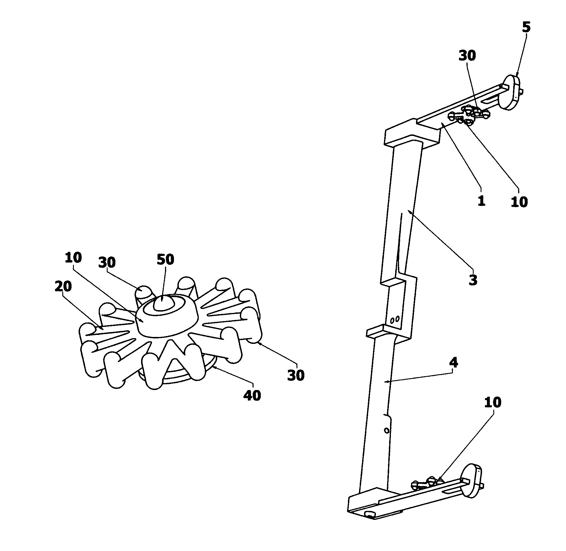
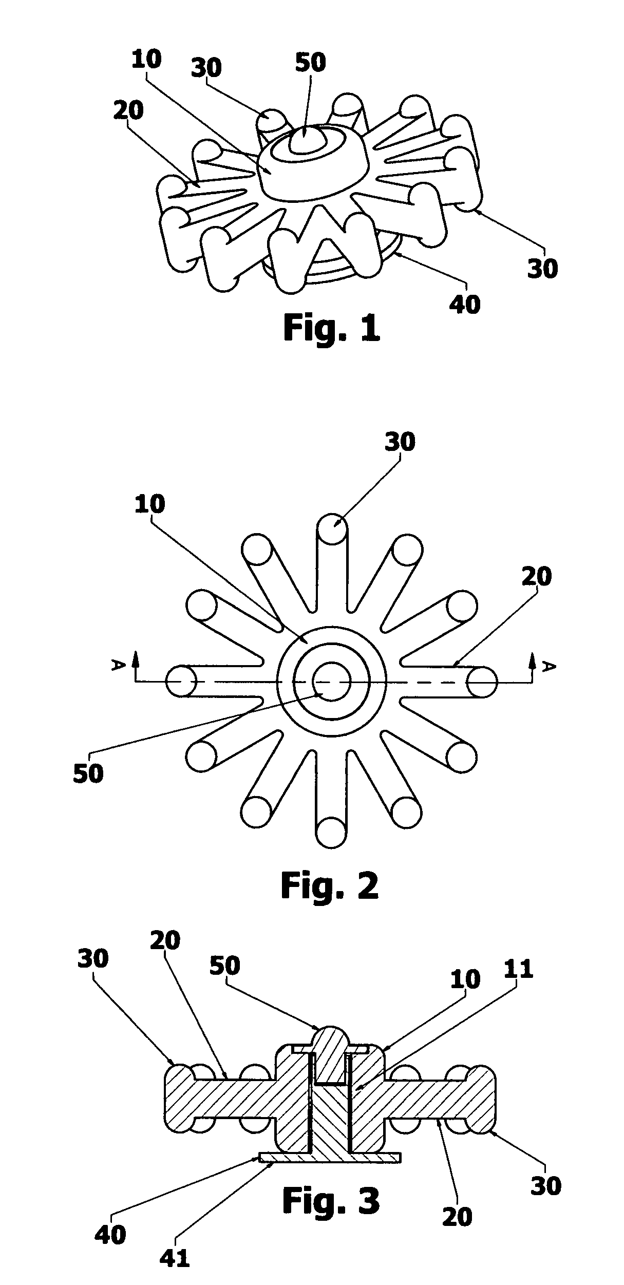
[0046]FIGS. 1-3 show a device 10 for reducing vibration and shock in a solid limb archery bow according to one preferred embodiments of this invention. This embodiment show device with twelve arms 20 with hemispherical contacts 30 top and bottom of arms 20. The bottom contact 30 is the one that makes contact with the limb when an arrow is released from an archery bow, the top is for cosmetic purposes as well as adding mass to the end of the arms 20. FIG. 3 shows the cross sectional view of the invention. Integrated base and stem 40 is inserted through the passage 11 of the body 10 and held in place by the retaining cap 50. The integral base and stem 40 are of a rigid plastic allowing only the arms 20 with hemispherical contacts 30 from device 10 to move. This version of the preferred embodiment uses an adhesive or double stick tape to mount to a solid limb bow, the adhesive or tape is placed on the flat bottom of base 40 at 41.

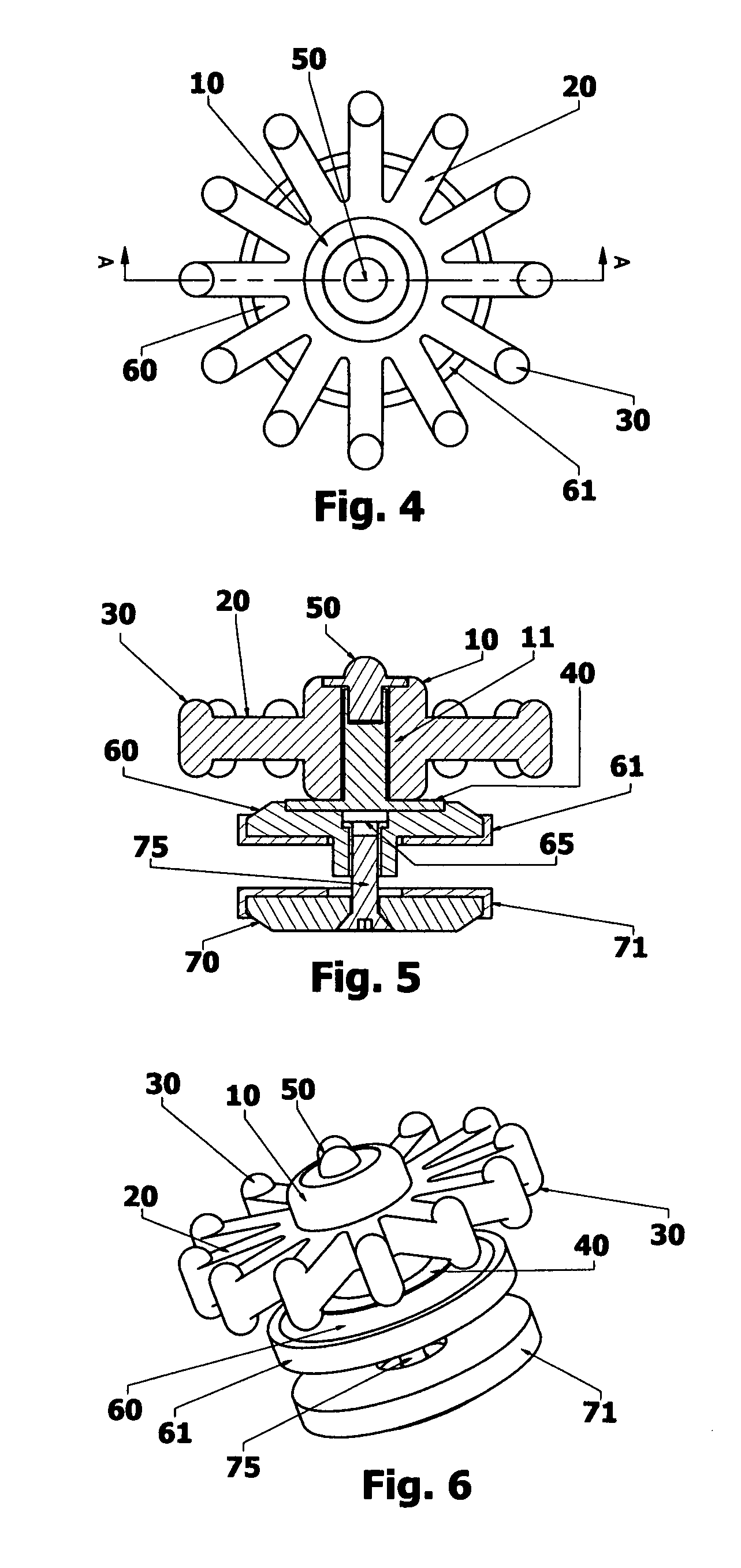
[0047]FIGS. 4-6 show a device 10 for reducing vibration ...


PUM


Abstract

Disclosed is a device made of a soft, flexible elastomer with freely movable members for use as a vibration dampener on an archery bow limb. Upon release of an arrow from an archery bow, the damper members reactively contact and rebound against the bow limb. The device can be installed on a mount to attach to both solid limb and split limb bows at the same general location on both the top and bottom limbs to greatly reduce the duration of vibration, the amount of hand shock and perceived noise generated upon release of an arrow from an archery bow.

Description

THE FIELD OF THE INVENTION[0001]The present invention is a device used for dampening vibrations of a bow limb after the release of an arrow from an archery bow.BACKGROUND OF INVENTION[0002]Archery bows generate excessive noise when fired due to the considerable amount of vibration of the archery bow limbs. Other bow limb vibration dampeners position the greater mass of the elastomer device at the end furthest from the mount. This allows the greater mass of the device to wiggle and jiggle in free space without making contact with the bow limb. Although these devices were effective in reducing vibrations in older bows, they are not as effective when attached to newer bows that have a generally parallel limb arrangement. This is due to the unique forces placed on the bow limbs upon the release of an arrow from an archery bow. The reason that more manufactures have started using this parallel limb mounting arrangement is because it has been observed that hand shock, vibration and noise ...

Claims


Application Information

Patent Timeline
Patent Type & Authority Patents(United States)
IPC IPC(8): F41B5/20
CPCF41B5/1426
Inventor WRIGHT, STUART DUANE
Owner WRIGHT STUART D
Why Eureka
Try Eureka