Implement having adjustable handle

a technology of implements and handles, applied in the field of implements, can solve problems such as ergonomic positions of hands, and achieve the effects of convenient and rapid loosing, rapid change, and convenient handling

Active Publication Date: 2010-05-04
ANDREAS STIHL AG & CO KG
View PDF19 Cites 8 Cited by
  • Summary
  • Abstract
  • Description
  • Claims
  • Application Information

AI Technical Summary

Benefits of technology

[0024]Due to the fact that the implement of the present application has a second handle, the implement can also be guided with two hands, in other words in a two-handed operation. This reduces operator fatigue. In this way, ergonomic grip operations that permit a low-fatigue operation are possible not only for the one-handed operation but also for the two-handed operation. Since the second handle can be displaced or adjusted into a non-operative position, it is possible, where this is advantageous, to have the previously known one-handed operation. The second handle, in addition to the previous one-handed operation, thus also enables a two-handed operation, so that the implement can be used in various ways and permits a low-fatigue operation.
[0026]In the operating position for two-handed operation, the ends of the two handles that face away from the handle frame are advantageously inclined relative to one another. This results in an ergonomic position of the hands during the two-handed operation and during the one-handed operation. The first handle can be mounted on the handle frame so as to be rotatable about its longitudinal direction. As a result, in both operating positions the first handle can have approximately the same orientation relative to the implement, so that for example the arrangement of control elements or the like on the first handle is the same in both operating positions. The first handle is preferably pivoted by about 90° relative to the handle frame between the first and the second operating positions. The pivot angle of the first handle in this connection expediently corresponds to the pivot angle of the handle frame between the two positions, whereby the first handle is rotated in the opposite direction to the handle frame, so that the absolute orientation of the first handle remains approximately the same. A straightforward configuration results if the first handle is secured to the handle frame via a fixing means, in particular a setscrew, that is secured in different positions on the handle frame in the first and the second operating positions. The setscrew can be easily and rapidly loosened by the operator and changed over. As a result, a rapid, simple change between the two operating positions can be achieved. To fix the handle in the various positions, no additional components, other than the setscrew that is required anyway for securement, are necessary. The control elements, especially the throttle trigger for operating a drive motor of the implement, can be arranged on the first handle.
[0027]The two handles can be secured to a tubular section of the implement. The handles thus serve to guide the tubular section of the implement relative to the ground. An ergonomic arrangement of the two handles is achieved if in the operating position for the two-handed operation, the two handles are disposed in the plane that lies transverse, in particular approximately perpendicular, to the longitudinal direction of the tubular direction. In the operating position for a one-handed operation, the two handles are preferably disposed in a plane that lies approximately parallel to the longitudinal direction of the tubular section. As a result, both handles can be disposed in the region of the tubular section. A good introduction of force into the tubular section from the first handle thus results, so that the implement is easy to handle. The second handle is preferably also disposed in the region of the tubular section, thus avoiding an obstruction to the operator by the second handle.
[0029]A straightforward configuration of the handle frame is achieved if a section of the handle frame extends on that longitudinal side of the tubular section that is opposite the two handles. The handle frame is preferably secured to the tubular section of the implement by means of a detachable clamp. Due to the fact that the clamp is detachably disposed on the tubular section, instead of the clamp for the handle frame having two handles, a clamp for the arrangement of a single handle can be secured to the tubular section. As a result, the implement can also be operated as previously with a single handle. The clamp expediently has a mounting support in which the handle frame is disposed in such a way as to be rotatable about the axis of rotation. As a result, a rotatability of the handle frame can be realized in a structurally straightforward manner.
[0031]A versatile use of an implement to which is secured a first handle can be provided if the first handle is secured to a tubular section of the implement via a clamp, whereby a handle is detachably mounted on the clamp and the clamp is mounted on the tubular section. As a result, it is possible to exchange the first handle by a handle frame to which is secured a second handle, so that the implement can be guided not only with a single handle but also with two handles. This enables a flexible utilization of the implement. By means of the detachable mounting of the first handle on the clamp, the handle can be mounted on a handle frame, so that the control elements disposed on the first handle are available to the operator. It can be advantageous to have only one clamp for fixation of either the handle frame or a single handle to the tubular section. It can be advantageous that the clamp is detachably mounted on the tubular section. In this way it is possible to have different clamps for fixation of the handle or the handle frame to the tubular section.

Problems solved by technology

This results in an ergonomic position of the hands during the two-handed operation and during the one-handed operation.

Method used


Image

  • Implement having adjustable handle
  • Implement having adjustable handle
  • Implement having adjustable handle

Examples


Embodiment Construction

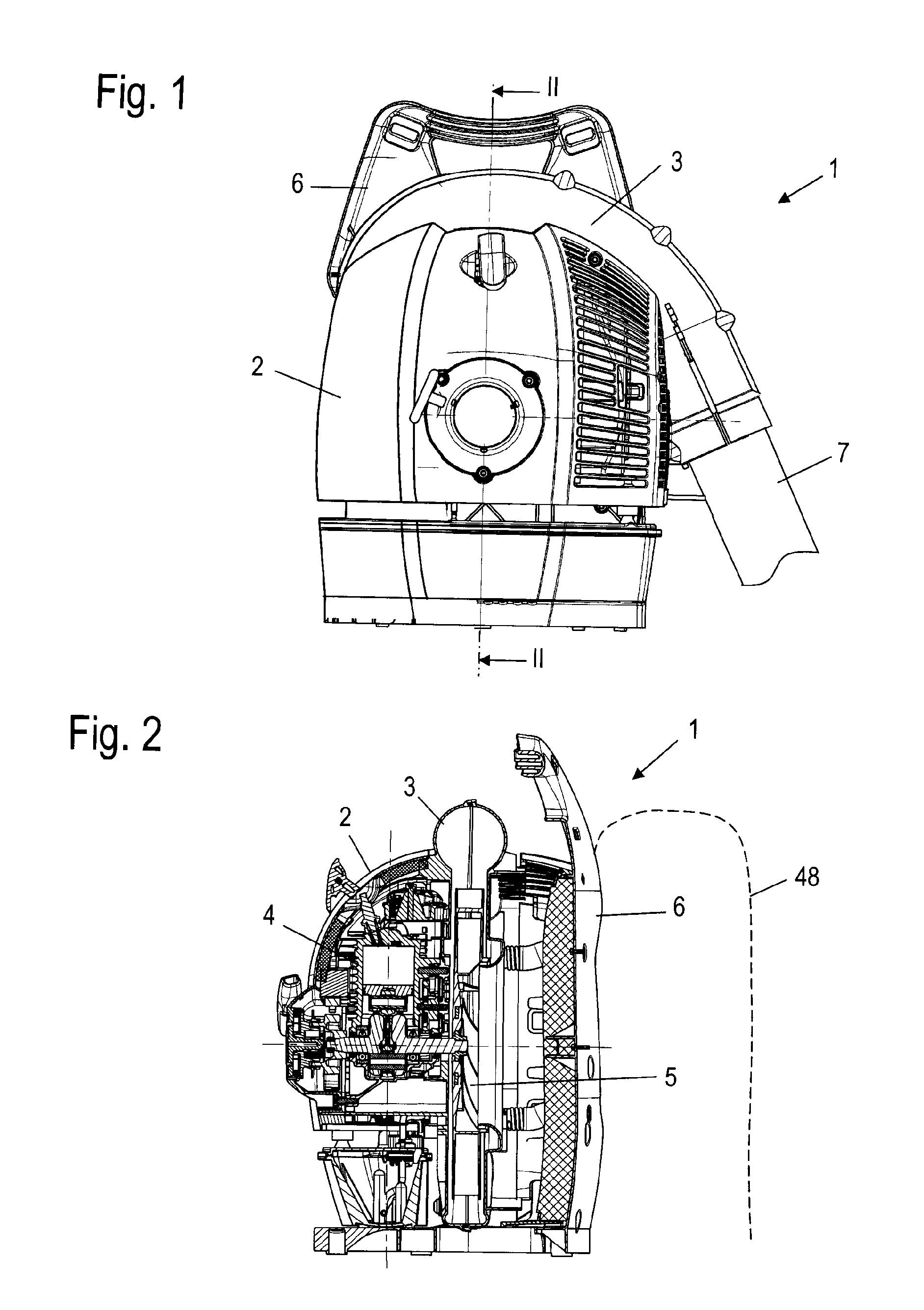
[0033]Referring now to the drawings in detail, the blower 1 shown in FIGS. 1 and 2 has a housing 2 in which is disposed a drive motor 4 which is preferably an internal combustion engine, such as a two-cycle engine or a four-cycle engine. The drive motor 4 drives an impeller 5 that conveys air into a blower spiral or volute 3, on which is disposed a blower or discharge tube 7. The housing 2 is secured to a backpack 6, so that the operator 48 can carry the blower 1 on his or her back. The blower tube 7 is guided around the body of an operator, is held by the operator, and is guided over the ground, so that dirt, leaves or the like can be removed from the ground. By means of the blower or discharge tube 7, the implement can also be used as a sprayer or as a suction device.

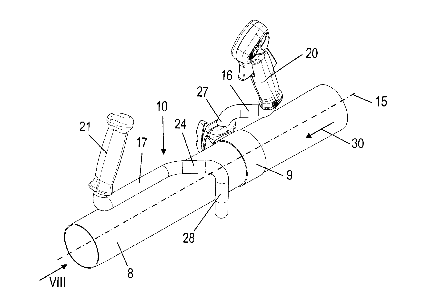
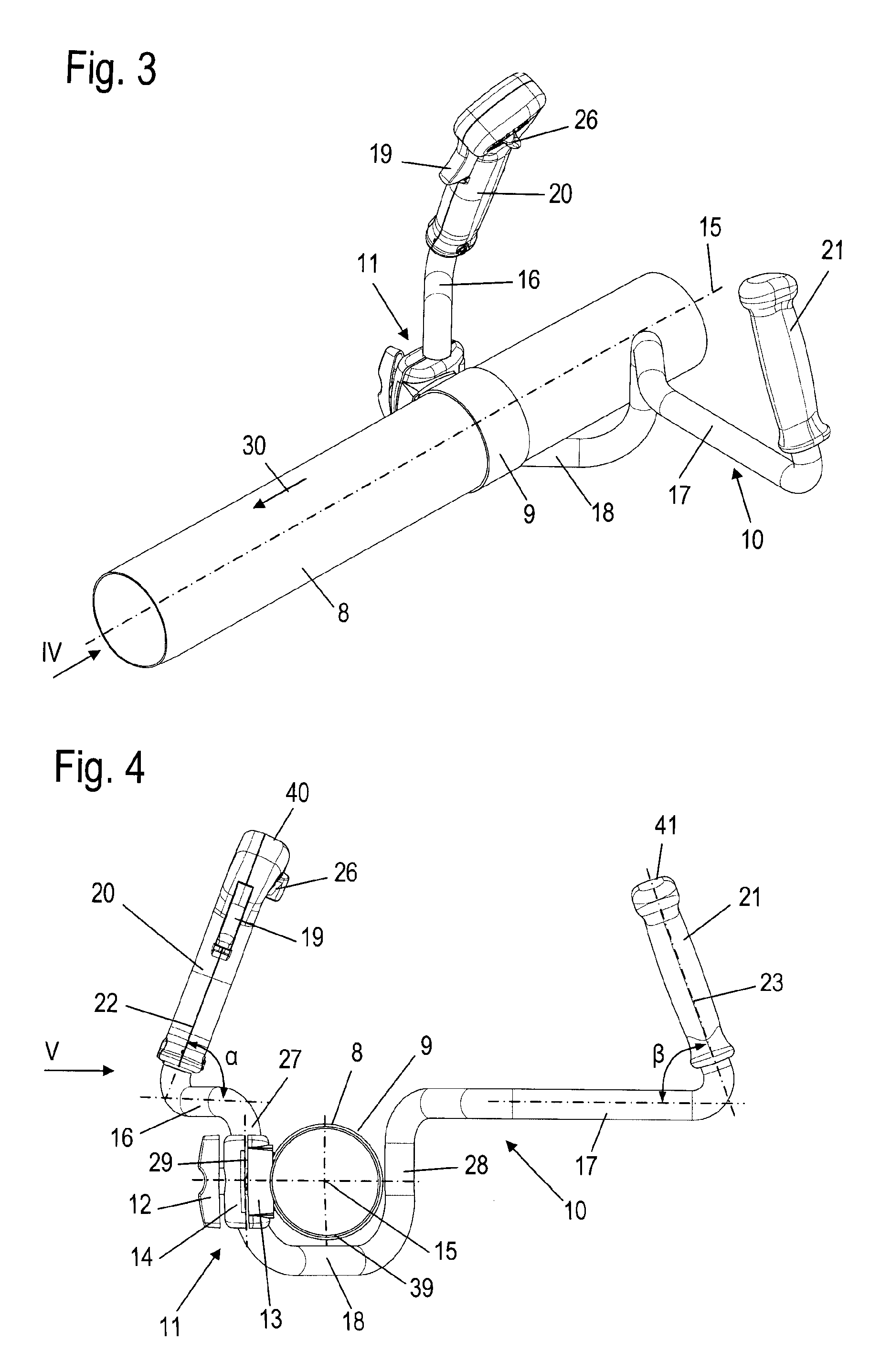
[0034]For guiding the blower tube 7, the blower 1 has the grip or handle frame 10 shown in FIG. 3; secured to the handle frame 10 are a first handle 20 and a second handle 21. The handle frame 10 is formed of a bent t...


PUM


Abstract

An implement comprising a first handle, on which are disposed control elements for the implement, and a second handle. The first handle is adjustable between a first operating position for a two-handed operation in which the implement is adapted to be guided by both the first handle and the second handle, and a second operating position for one-handed operation in which the implement is adapted to be guided by the first handle.

Description

[0001]The instant application should be granted the priority date of Sep. 28, 2005 the filing date of the corresponding German patent application 10 2005 046 227.8-15.BACKGROUND OF THE INVENTION[0002]The present invention relates to an implement on which is secured a first handle, whereby the control elements, in particular the throttle trigger for operating a drive motor of the implement, are disposed on the first handle.[0003]US 2005 / 0132531 A1 discloses an implement, namely a blower, having a handle for guiding the blower tube. The handle is disposed above the blower tube, and can be grasped ergonomically and conveniently only with one hand of the operator, so that the blower is suitable only for one-handed operation. Guiding the blower tube with only one hand can lead to operator fatigue.[0004]It is therefore an object of the present application to provide an implement of the aforementioned general type that permits a fatigue-free operation and a versatile use.BRIEF DESCRIPTION ...

Claims


Application Information

Patent Timeline
Patent Type & Authority Patents(United States)
IPC IPC(8): A47L5/00A47L9/00B25G1/10B25G3/32
CPCB25F5/026Y10T16/498Y10T16/469A01D34/90A01G3/06E01H1/08
Inventor HITTMANN, MARKUSGAESE, UWELANGHANS, KLAUS
Owner ANDREAS STIHL AG & CO KG
Why Eureka
Try Eureka