Inhalation device for transpulmonary administration

a technology of inhalation device and transpulmonary administration, which is applied in the direction of valve, respirator, operating means/releasing devices, etc., can solve the problems of reducing pulmonary capacity, burdening users (patients), and children, and reducing pulmonary capacity, so as to reduce the diameter of the inhalation flow path

Inactive Publication Date: 2010-05-04
OTSUKA PHARM CO LTD
View PDF33 Cites 60 Cited by
  • Summary
  • Abstract
  • Description
  • Claims
  • Application Information

AI Technical Summary

Problems solved by technology

Such an inhalation device disadvantageously places a burden on users (patients) who have reduced pulmonary capacity or children (patients) when generating the air impact with his / her inhalation-induced pressure.
However, because fine particles easily coalesce / agglomerate, they tend to form coalesced or agglomerated masses due to disturbances in the air flow within the mouth-side flow path of the mouthpiece that are caused when the auxiliary air is mixed with air containing the pulverized pharmaceutical composition.

Method used


Image

  • Inhalation device for transpulmonary administration
  • Inhalation device for transpulmonary administration
  • Inhalation device for transpulmonary administration

Examples


embodiment 1

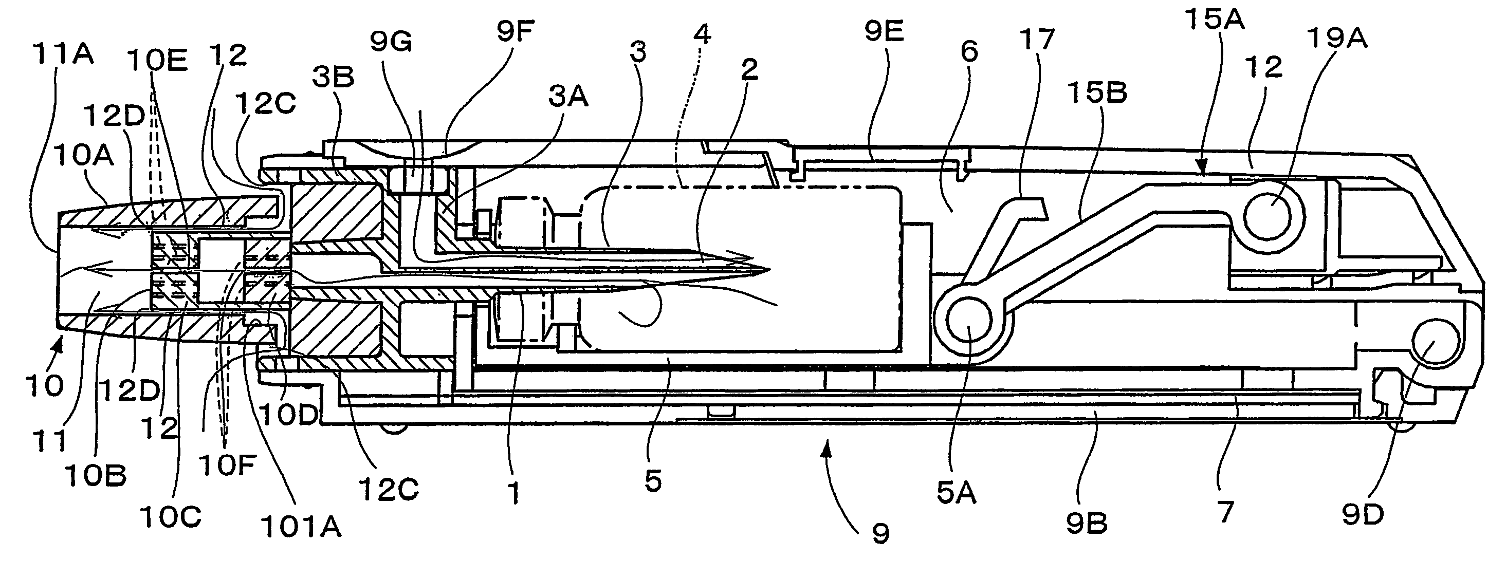
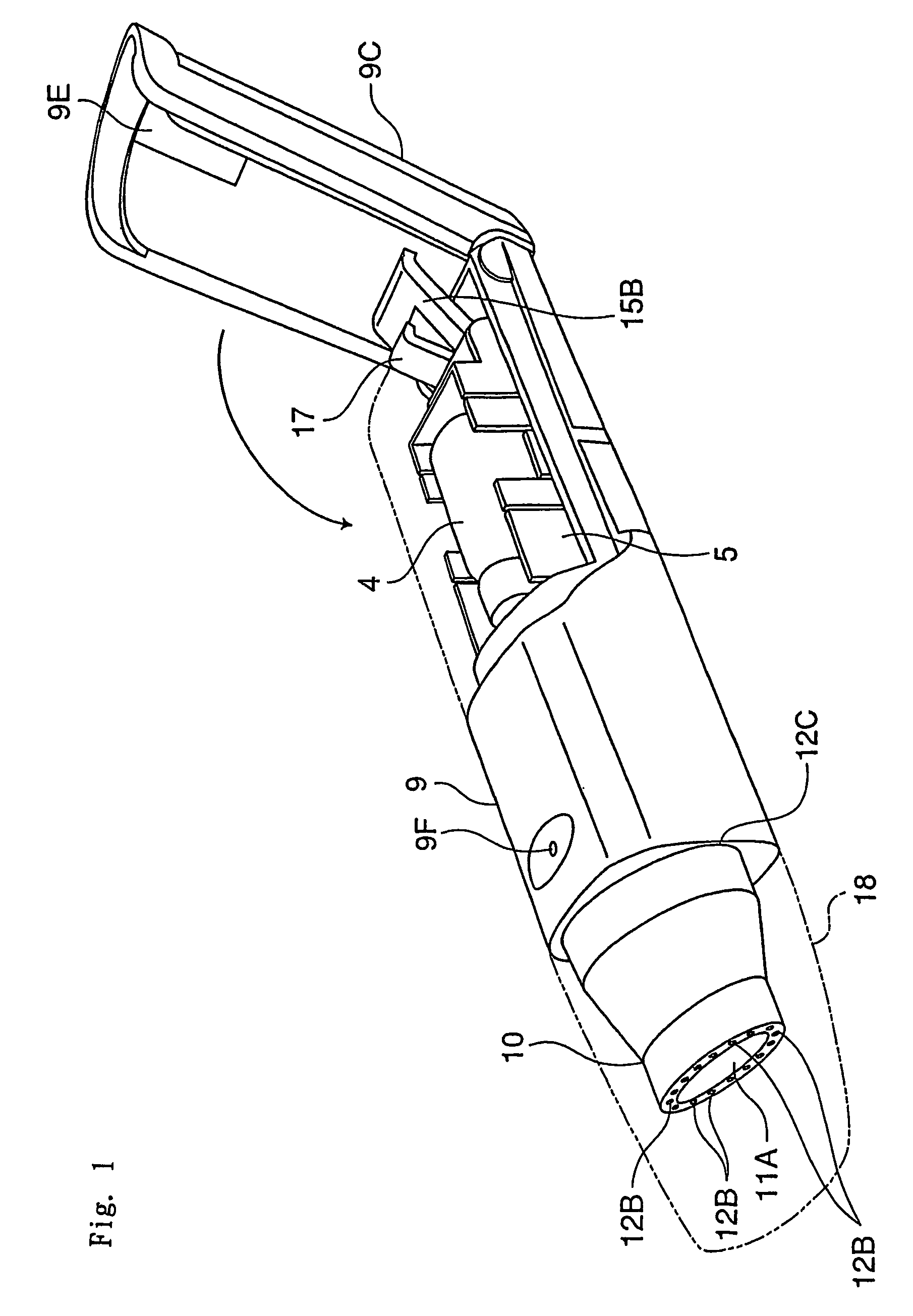
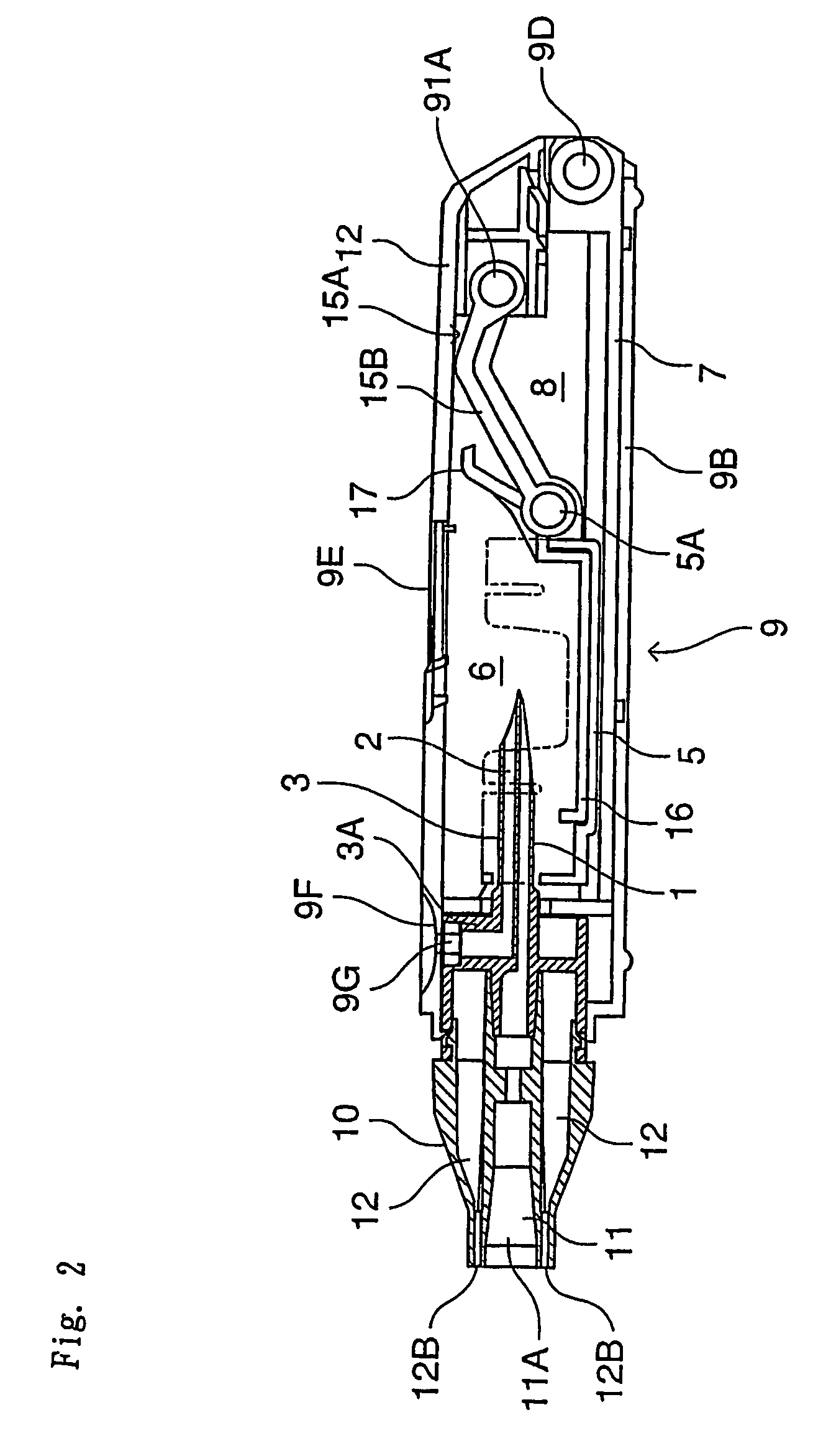
[0059]The inhalation device in this embodiment comprises a needle part 3 (an example of an unsealing member) in which are formed an inhalation flow path 1 and an air inlet flow path 2, a holder part 5 for containing a vessel 4 which contains one dose of pharmaceutical composition A and is sealed by a stopper 4a (an example of a sealing member), a chamber 6 for housing the vessel 4 of the holder part 5, a guide part 7 for guiding the holder part 5 in the axial direction of the needle part 3, and a holder operating part 15 for advancing and retreating the holder part 5 along the guide part 7; these are all housed in a tubular housing 9. Moreover, a mouthpiece 10 is provided at a tip of the housing 9.

[0060]The pharmaceutical composition A can be pulverized into fine particles having a particle size suitable for transpulmonary administration by an air-generated impact that flows into the vessel. The present embodiment employs a freeze-dried composition, which will be explained in more d...

embodiment 2

[0079]An inhalation device of the present embodiment is provided with two dividers 13 and 131 that are formed along the mouth-side flow paths 11 and 111 of the mouthpiece 10 at appropriately spaced intervals as shown in FIGS. 9 and 10. The components constituting the device other than the mouthpiece 10 are the same or similar to those of the first embodiment, and thus the same or similar components are designated by the same numerals as in the first embodiment, and their detailed descriptions are omitted here.

[0080]A single orifice 13A, the center of which is positioned at the center of the axis of the mouth-side flow path 11 of the mouthpiece 10, is formed at the divider 13 in the front part of the mouthpiece. A plurality of orifices 13A are provided at substantially equally spaced intervals at the divider 131 in the rear part of the mouthpiece, as shown in FIG. 11.

[0081]The mouthpiece 10 is comprised of two separable parts: a front part and a rear part. The divider 13 is formed in...

embodiment 3

[0086]As shown in FIGS. 13 through 15, the mouthpiece 10 is provided with an outer shell 10A, a tubular internal member 10C having a divider 10B, and a dividing block 10D. The composition of the inhalation device other than the mouthpiece 10 is the same as in the first embodiment, and their detailed descriptions are omitted here.

[0087]The mouthpiece 10 is assembled by fitting the internal member 10C into the outer shell 10A from the rear, and fitting the dividing block 10D into the internal member 10C from the rear. A plurality of spacers 101C project along an outer circumferential surface of the internal member 10C of the rear side at predetermined spaced intervals in the circumferential direction. A step part 101A is formed at an inner circumferential surface of the outer shell 10A throughout its length in the circumferential direction. The spacers 101C are fitted into the step part 101A of the outer shell 10A, and thus a cylindrical space is formed between the outer shell 10A and...


PUM


Abstract

An inhalation device for transpulmonary administration comprises: a chamber (16) for containing a pharmaceutical composition which is pulverized into fine particles by an air-generated impact for dispersal in air; an air inlet flow path (2) for introducing to the chamber (16) outside air to apply the air-generated impact to the pharmaceutical composition and for injecting the outside air toward the pharmaceutical composition; an inhalation flow path (1) for inhaling the pulverized pharmaceutical composition; a housing (9) for accommodating the chamber (16), the air inlet flow path (2), and the inhalation flow path (1); a mouthpiece (10) provided at one end of the housing (9), the mouthpiece (9) being provided with a mouth-side flow path (11) which communicates with the inhalation flow path (1), and an auxiliary flow path (12).

Description

TECHNICAL FIELD[0001]The present invention relates to a self-inhaling type inhalation device for transpulmonary administration.BACKGROUND OF THE INVENTION[0002]Such inhalation devices are provided with a chamber for containing a pharmaceutical composition, and are configured in such a way that outside air is introduced to the chamber by the inhalation-induced pressure of a user (patient) to apply an air-generated impact to the pharmaceutical composition, thus pulverizing the pharmaceutical composition into fine particles so that the user (patient) can inhale the pulverized pharmaceutical composition into the lungs from the mouth-side flow path (disclosed in Japanese Unexamined Patent Application No. 1999-221280, for example).[0003]Such an inhalation device disadvantageously places a burden on users (patients) who have reduced pulmonary capacity or children (patients) when generating the air impact with his / her inhalation-induced pressure.[0004]This burden on the user can be reduced ...

Claims


Application Information

Patent Timeline
Patent Type & Authority Patents(United States)
IPC IPC(8): A61M15/00A61M11/00
CPCA61M15/0028A61M15/0033A61M2206/16A61M2202/064A61M11/001A61M15/00
Inventor YAMASHITA, CHIKAMASAMATSUSHITA, HITOSHIIBARAGI, SHIGERUAKAGI, AKITSUNA
Owner OTSUKA PHARM CO LTD
Why Eureka
Try Eureka