
Multiple coin actuation mechanism having pivotal latch preventing coin removal from carrier wheel recess

Inactive Publication Date: 2010-05-04
CHANG KIL JAE
View PDF3 Cites 3 Cited by
  • Summary
  • Abstract
  • Description
  • Claims
  • Application Information

AI Technical Summary

Benefits of technology

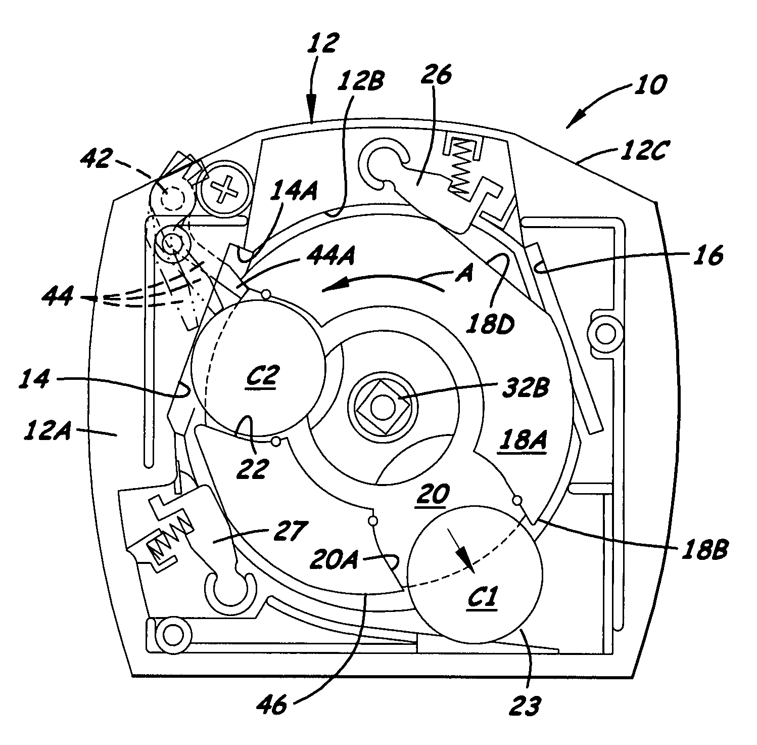
[0006]The present invention provides a vending machine coin actuation mechanism and method designed to satisfy the aforementioned need. The approach of the present invention provides for the positioning and operation of a coin removal blocking latch that offers no obstruction to the first coin as it is inserted through the first coin slot into the first coin recess on the carrier wheel. Also, rather than blocking the first coin slot as the second coin recess becomes aligned with the first coin slot, the latch is biased toward the carrier wheel so as to yieldably ride over the second coin while still engaging and pressing against the second coin so as to retain it in the second coin recess as the rotating carrier wheel approaches and passes the first coin slot. As the second coin recess passes the first coin slot the latch remains in alignment with the second coin recess so as to prevents removal of the second coin from the second coin recess on the carrier wheel. Hence, the latch does not actually directly block access to the first coin slot but instead prevents removal of the second coin from the second coin recess on the carrier wheel.

Problems solved by technology

However, a problem with this design in that the use of the rocker bar coin blocking device increases the complexity and cost of the design over that of the conventional prior art coin actuation mechanisms.
Frequently, users inserting the first coin will think the latch is an obstruction that needs to be dealt with and some users may damage the machine in attempting to force the coin against the latch.

Method used


Image

  • Multiple coin actuation mechanism having pivotal latch preventing coin removal from carrier wheel recess
  • Multiple coin actuation mechanism having pivotal latch preventing coin removal from carrier wheel recess
  • Multiple coin actuation mechanism having pivotal latch preventing coin removal from carrier wheel recess

Examples


Embodiment Construction

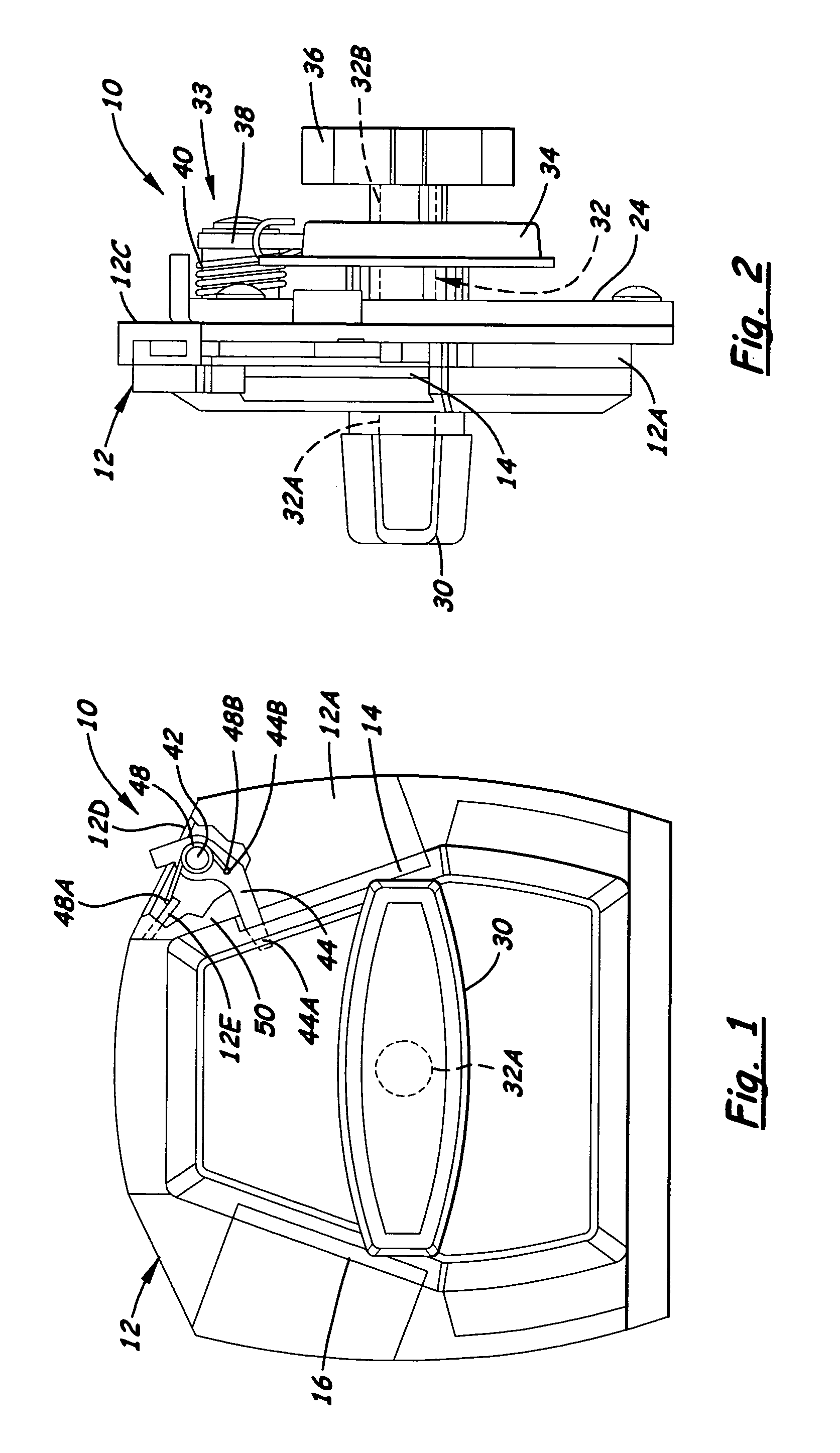
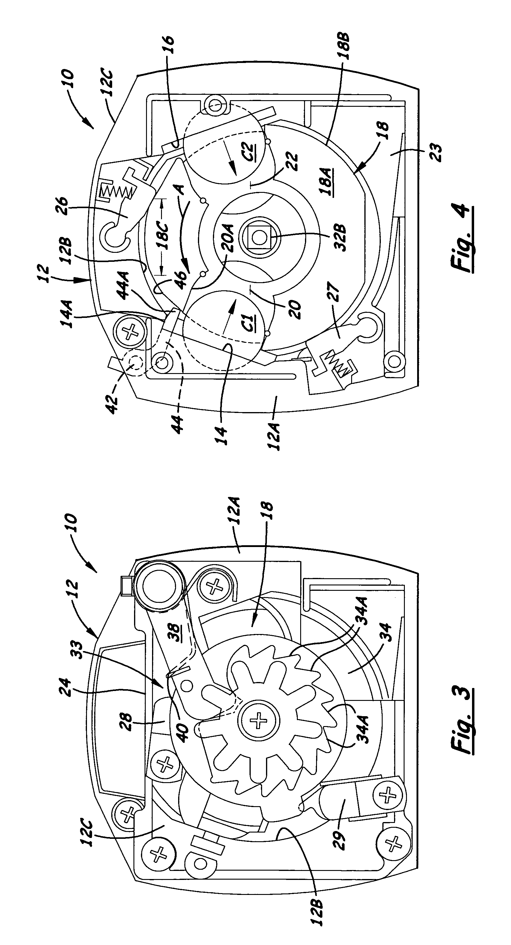
[0017]Referring to the drawings and particularly to FIGS. 1 to 6, there is illustrated a multiple coin actuation mechanism, generally designated 10, of the present invention. It will be referred to hereinafter as the “improved” actuation mechanism 10. The improved actuation mechanism 10 retains the structural components of a prior art multiple coin actuation mechanism, as is substantially disclosed in U.S. Pat. No. 7,222,711, by the same inventor as herein. The improved actuation mechanism 10, however, introduces modifications in relationships between components of the prior art actuation mechanism which, though seeming small, achieve a relatively large improvement in the ease of operation of the improved actuation mechanism 10 over that of the prior art actuation mechanism. These modifications and the resulting improvement in ease of operation will become clear hereinafter. However, the structural components of the prior art actuation mechanism retained by improved actuation mechan...


PUM


Abstract

A multiple coin actuation mechanism has a latch biased to an inward home position with its inner end extending through an upstream side of a first coin slot of a stationary front cover plate toward a rotatable carrier wheel and generally alongside an unobstructed path for insertion of a first coin through the first coin slot into a first coin recess of the carrier wheel. The latch is pivotally yieldably movable away from the carrier wheel due to engagement with a second coin in a second coin recess in the rotatable carrier wheel, as the second coin is brought into alignment with the first coin slot, to allow the second coin to pass under the latch while the latch remains in contact with the second coin, preventing its removal from the second coin recess outwardly through the first coin slot, as the carrier wheel rotates past the first coin slot.

Description

[0001]This patent application claims benefit of U.S. provisional application No. 61 / 062,721 filed Jan. 29, 2008.BACKGROUND OF THE INVENTION[0002]The present invention generally relates to vending machines and, more particularly, is concerned with a multiple coin actuation mechanism having a pivotal latch preventing coin removal from a carrier wheel recess.[0003]U.S. Pat. Nos. 5,657,848 and 5,924,542 to Schwarzli disclose a prior art multiple coin actuation mechanism for a vending machine. The coin actuation mechanism has a front cover plate with first and second coin slots, a rotatable coin carrier wheel with first and second coin recesses angularly spaced apart on one face of the carrier wheel and aligned with the first and second coin slots of the cover plate when the carrier wheel is in a home position for the user to deposit a coin into each of the coin recesses, a rear retainer plate overlying the carrier wheel and fixedly attached to the front cover plate, and a rocker bar fix...

Claims


Application Information

Patent Timeline
IPC IPC(8): G07F5/02G07F11/00G07F5/10G07F13/00G07F15/00G07F17/00G07F5/00
CPCG07F5/20G07F1/02
Inventor CHANG, KIL JAE
Owner CHANG KIL JAE
Learn More