Housing with hidden ventilation holes

a technology of ventilation holes and housings, which is applied in the direction of electrical apparatus casings/cabinets/drawers, cooling/ventilation/heating modifications, packaging, etc., can solve the problems of reducing the sales of such electronic devices in the market, adversely affecting the normal functioning of an electronic device, and shortening the useful product life of an electronic device. , to achieve the effect of maintaining the structural strength of the housing

Active Publication Date: 2010-05-11
D-LINK
View PDF2 Cites 28 Cited by
  • Summary
  • Abstract
  • Description
  • Claims
  • Application Information

AI Technical Summary

Benefits of technology

[0006]It is an object of the present invention to provide a housing of an electronic device having a plurality of hidden ventilation holes comprising an intermediate frame, an upper shell, and a lower shell wherein the intermediate frame comprises an upright flange along its outer edges, the upper shell and the lower shell both have its edge secured to a inner edge inside the flange of the intermediate frame, the upper shell comprises a plurality of spaced first cavities formed along the lower edge, the lower shell comprises a plurality of spaced second cavities formed along the upper edge, and both the first and second cavities are concealed by and hidden behind the flange when the intermediate frame is assembled with the upper shell and the lower shell respectively. By utilizing this housing formed with hidden ventilation holes, the ventilation holes are concealed, a structural strength of the housing is maintained, and the housing is aesthetic.

Problems solved by technology

Thus, excessive high working temperature may adversely affect a normal functioning of an electronic device if it does not have an effective heat dissipation means.
To the worse, a useful product life of the electronic device may get shortened quickly.
And in turn, it may greatly decrease sales of such electronic devices in the market.
However, structural intension of the housing of the electronic device may be decreased significantly due to many ventilation holes.
Thus, the structurally weak housing of such electronic device is subject to deformation or damage due to collision during transportation.
Further, the provision of ventilation holes on the housing of an electronic device is not aesthetic as viewed by many designers of the art in consideration of the fast development of electronic devices.
Also, drawbacks (e.g., reduction of structural intension and being not aesthetic) associated with the provision of ventilation holes on the housing are required to be eliminated from an electronic device.
Another drawback of the provision of ventilation holes is that the ventilation holes, in accordance with the specifications of related rules, are required to be sufficiently small.
Otherwise, sparks due to malfunction of circuitry of an electronic device may spread to the outside of the electronic device through the ventilation holes and may even cause accident.
This potential danger is not desired.

Method used


Image

  • Housing with hidden ventilation holes
  • Housing with hidden ventilation holes
  • Housing with hidden ventilation holes

Examples


Embodiment Construction

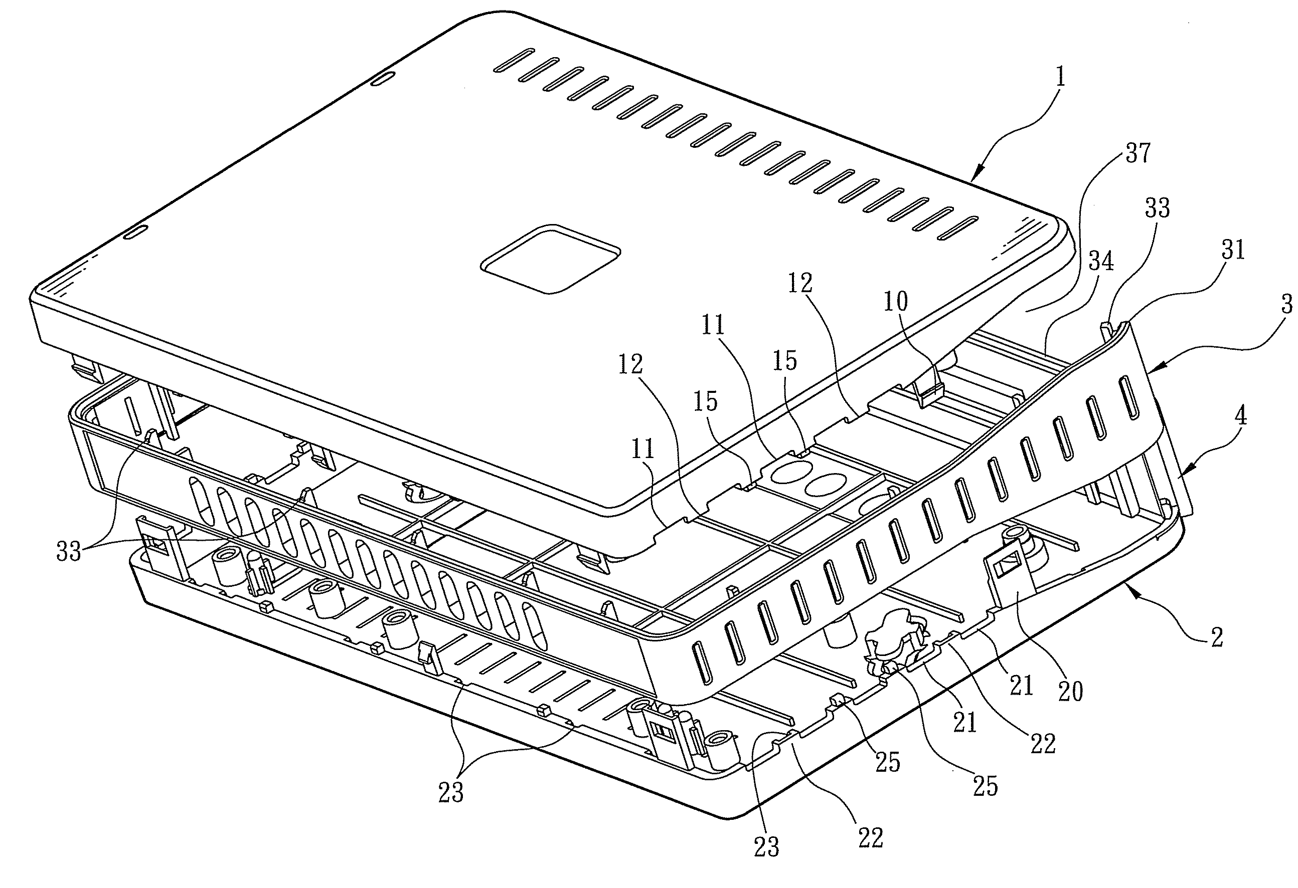
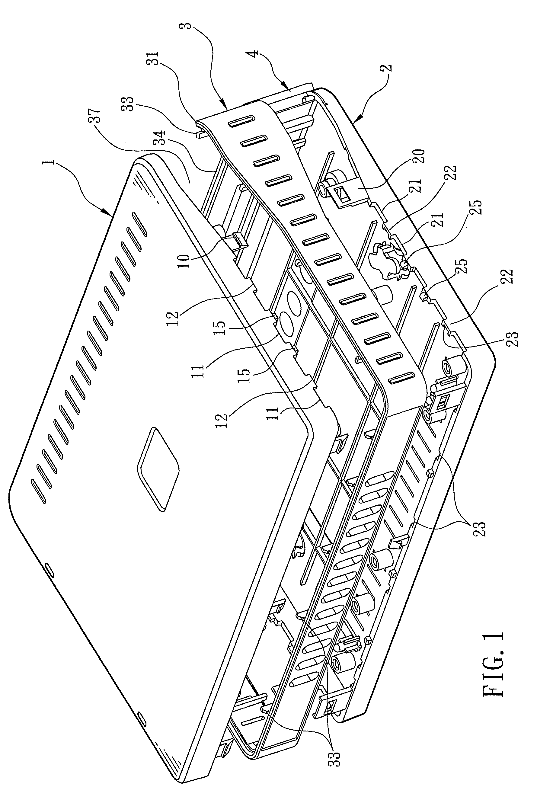
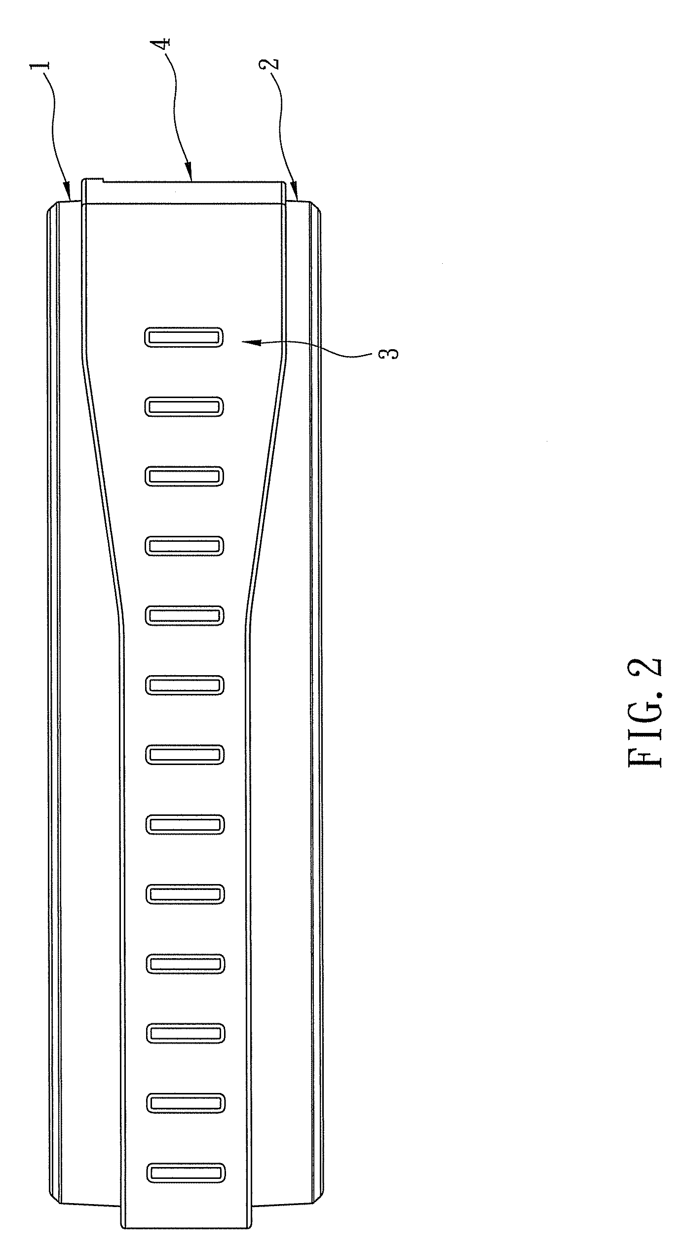
[0015]Referring to FIGS. 1 and 2, a housing of an electronic device having hidden ventilation holes in accordance with a preferred embodiment of the invention is shown. The housing comprises an upper shell 1, a lower shell 2, and an intermediate frame 3. The intermediate frame 3 is hollow and is mounted between the upper shell 1 and the lower shell 2. The intermediate frame 3 comprises an U-shaped upright flange 31 along outside of its three edges. Edges of both the upper shell 1 and the lower shell 2 are secured to top and bottom edges inside of the flange 31 respectively. The upper shell 1 comprises a plurality of first fastening members (e.g., latches as shown) 10 extended downward from the edge of the upper shell 1 to be proximate to the lower shell 2. Correspondingly, the lower shell 2 comprises a plurality of second fastening members (e.g., risers having an aperture as shown) 20 extended upward from the edge of the lower shell 2 to be proximate to the upper shell 1. The second...


PUM


Abstract

The present invention is to provide a housing of an electronic device having a plurality of hidden ventilation holes, which comprises an intermediate frame, an upper shell and a lower shell, wherein the intermediate frame comprises an upright flange along the outer edges thereof, the upper shell and the lower shell respectively have its edge secured to an inner edge inside the flange of the intermediate frame, the upper shell and the lower shell both comprise a plurality of spaced cavities formed along the edge of the upper shell and the lower shell, and both the cavities are concealed behind the flange when the intermediate frame is assembled with the upper shell and the lower shell respectively, so as to maintain a structural strength of the housing and to be looked aesthetic.

Description

FIELD OF THE INVENTION[0001]The present invention relates to housing of electronic device, and more particularly to two sides of an intermediate frame respectively secured by an upper shell and a lower shell which both having a plurality of spaced cavities formed along the edge thereof, and these cavities are concealed behind a flange that extended from outer edge of the intermediate frame, so as to form hidden ventilation holes.BACKGROUND OF THE INVENTION[0002]This world has entered into a new era with information and electronic technologies being progressed rapidly. A wide variety of computer related advanced products and mobile communication products are commercially available. Moreover, network communication technology has known a fast development in recent years. Characteristics of these computer related advanced products and mobile communication products are comprised of compactness, multifunction, and low price, therefore people love to use these kinds of 3C products and even...

Claims


Application Information

Patent Timeline
Patent Type & Authority Patents(United States)
IPC IPC(8): B65D6/24
CPCH05K5/0213
Inventor CHO, CHENG-CHISU, YONG-JHIH
Owner D-LINK
Why Eureka
Try Eureka