Structure for connecting members

a technology for connecting members and connecting parts, applied in the direction of chairs, movable seats, transportation and packaging, etc., can solve the problems of poor appearance of the spring member, and achieve the effect of reducing the feeling of disharmony on the appearance due to the installation of the spring member and preventing the pivoting portion

Inactive Publication Date: 2010-05-11
KOKUYO CO LTD
View PDF93 Cites 188 Cited by
  • Summary
  • Abstract
  • Description
  • Claims
  • Application Information

AI Technical Summary

Benefits of technology

[0008]Consequently, the connecting portion between the spring member and the first member and the connecting portion between the spring member and the second member can adopt a structure in which the spring member is installed to the first member or the second member with screws or the spring member and the first member or the second member are formed integrally. As a result, a construction near the connecting portion is not formed in an unnaturally large diameter and the appearance of furniture can be arranged neatly by constructing the spring member so that it looks as part of the first and second members.
[0009]Particularly, if both the first member and the second member is frame-like member and the spring member is disposed substantially parallel to the first member and the second member, a portion in which the first and second frame member and the spring member are disposed is constructed into a shape in which two frame-like members are disposed substantially parallel to each other and consequently, feeling of disharmony on the appearance due to installation of the spring member can be reduced.
[0010]If the first member and the second member are pivoted to each other at end portions thereof, the pivoting portion can be prevented from being formed into an unnaturally large diameter by connecting the spring member to the first member and the second member instead of providing the pivoting portion with a torsion coil spring.
[0011]As an embodiment capable of securing the above-mentioned advantages preferably, the first member is lower frame element constituting a backrest lower portion of a chair and the second member is upper frame element constituting a backrest upper portion of the chair. Consequently, a structure which allows the upper portion of the backrest to be tilted backward following up a seated person's movement of warping his or her back and when the movement of warping his or hers back ends, a condition in which a reaction force is accumulated in the spring member to be released can be achieved without damaging the neat appearance of the chair seriously.
[0013]On the other hand, as a structure capable of easily obtaining an effect that the reaction force applied to the backrest is increased as the backrest is tilted backward largely, a structure that the first member is a base body which supports a seat and backrest of a chair and the second member is a back frame constituting at least part of the backrest of the chair.
[0015]Because if the structure for connecting members of the present invention is adopted, the structure for installing the spring member to the first member or the second member with screws or the like or forming the spring member and the first member or the second member integrally can be adopted for a connecting portion between the spring member and the first member and a connecting portion between the spring member and the second member, the appearance of the furniture can be arranged neatly without forming the construction near the connecting portion into an unnaturally large diameter.

Problems solved by technology

If such a twisting coil spring is exposed outside, substance may go into between the twisting coil spring and pivoting shaft so that a relative movement between the first and second members becomes unsmooth, which is a problem to be solved.
On the other hand, if a cover for wrapping such a twisting coil spring is provided, that cover needs to be provided in the vicinity of the pivoting shaft, so that apparently the diameter near the pivoting shaft increases largely as compared with the widths of the first and second members thereby generating such a disadvantage that its appearance is poor to see.

Method used


Image

  • Structure for connecting members
  • Structure for connecting members
  • Structure for connecting members

Examples


Embodiment Construction

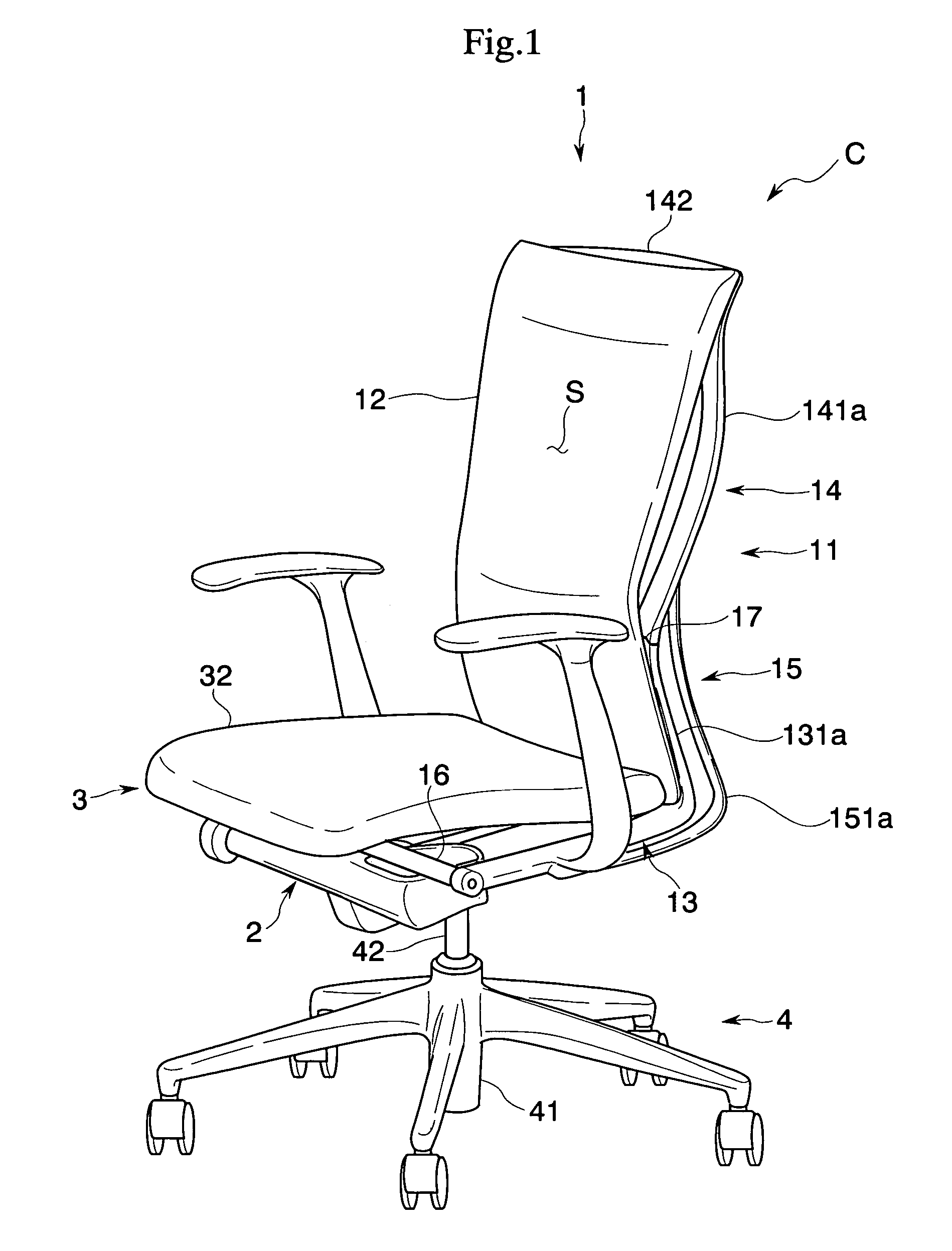
[0035]Hereinafter, the embodiment of the present invention will be described with reference to the accompanying drawings.

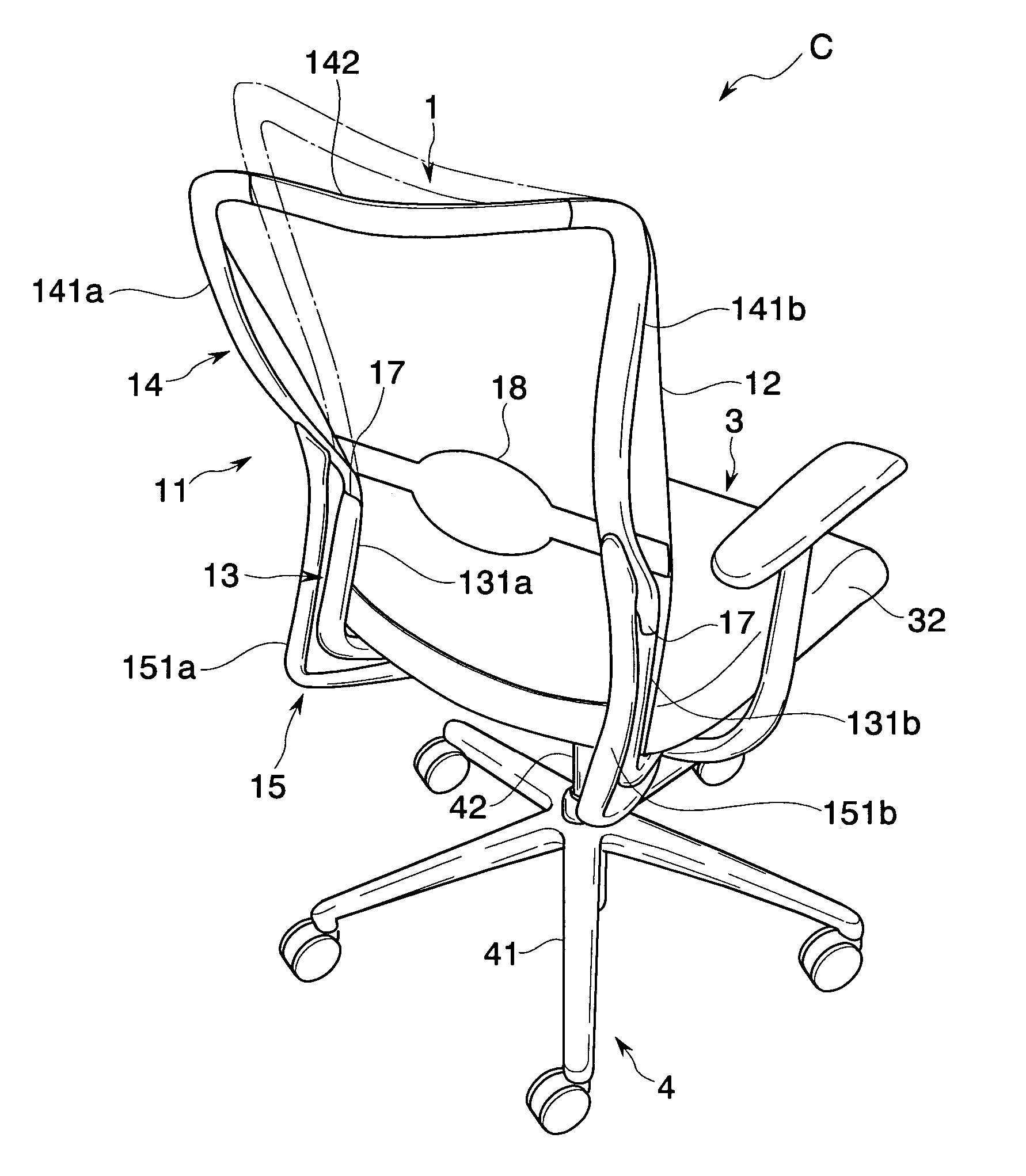
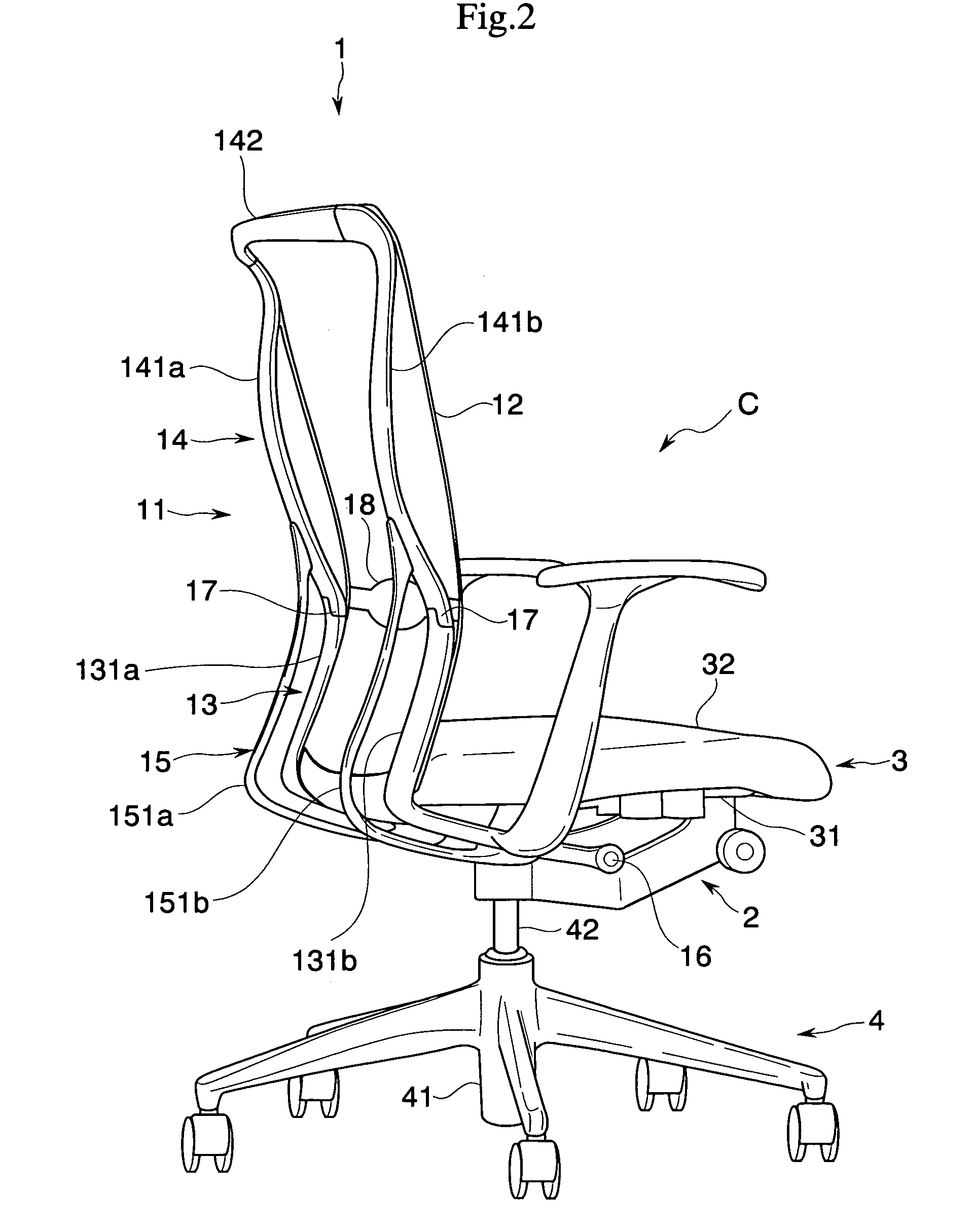
[0036]A chair of this embodiment, as shown in FIGS. 1 to 5, comprises a leg body 4, a base body 2 supported by the leg body 4, a seat 3 disposed on the base body 2 and a backrest 1 pivoted to the base body 2 through a horizontal support shaft 16 and can achieve synchronous rocking motion in which the seat 3 and the backrest 1 tilt interlockingly.

[0037]If speaking in detail, the leg body 4 comprises leg wing 41 having a plurality of casters and a leg support pillar 42 standing substantially perpendicularly from the center of the leg wing 41. The leg support pillar 42 can be projected or recessed vertically by expansion and contraction of a gas spring (not shown) provided between the leg wing 41 and the leg support pillar 42.

[0038]The base body 2 is fixed to the top end of the leg support pillar 42 and the heights of the seat 3 and the backrest 1 can be adjusted thr...


PUM


Abstract

A structure intends to arrange the appearance of furniture at a connecting portion between a first member having stiffness and a second member movable relative to the first member and having stiffness without forming the connecting portion in an unnaturally large diameter. More specifically, the present invention provides a structure for connecting members comprising: a first member having stiffness; a second member movable relative to the first member and having stiffness; and a spring member in which an end portion thereof is connected to the first member and other end portion thereof is connected to the second member so as to accumulate a reaction force by elastic deformation, wherein the spring member is formed into a frame-like shape extending along the first and second members.

Description

BACKGROUND OF THE INVENTION[0001]1. Field of the Invention[0002]The present invention relates to a structure for connecting members wherein a first member is connected to a second member movable relative to the first member via a spring member capable of storing a reaction force by elastic deformation.[0003]2. Description of the Related Art[0004]As a structure for connecting a first member having stiffness and a second member movable relative to the first member and having stiffness via a spring member disposed between the first and second members and capable of accumulating reaction force by elastic deformation, a variety of examples have been contemplated. For example, a structure in which the first member and second member are connected pivotably at their end portions and a twisting coil spring is disposed at this pivoting portion has been contemplated (see for example Japanese Patent No. 2616332 (see particularly paragraph 0020)).[0005]Then, in the structure described in the Jap...

Claims


Application Information

Patent Timeline
Patent Type & Authority Patents(United States)
IPC IPC(8): A47C3/00
CPCA47C1/03255A47C7/445A47C1/03261A47C7/4454
Inventor UEDA, NOBUYUKI
Owner KOKUYO CO LTD
Why Eureka
Try Eureka