Jewelry article for a lens of eyeglasses and a jewelry-installation tool for a pair of eyeglasses

a technology of eyeglasses and jewelry articles, which is applied in the field of jewelry articles, can solve the problems of the shift of the position of the first and the second magnets above mentioned, the possibility of losing the main body of the jewel, and the conventional jewelry of eyeglasses mentioned

Inactive Publication Date: 2010-05-11
CROSSFOR
View PDF9 Cites 29 Cited by
  • Summary
  • Abstract
  • Description
  • Claims
  • Application Information

AI Technical Summary

Benefits of technology

[0005]In view of the disadvantage above mentioned, the objective of this invention is to provide a jewelry article for a lens of eyeglasses and an installation tool for eyeglasses, which can prevent the main body of a jewel held by a magnet on a lens from losing by the fall.

Problems solved by technology

However, the conventional jewelry for eyeglasses mentioned above has a disadvantage, that the position of the first and the second magnets above mentioned shift when the main body of a jewel hits any object.
Then, the main body of a jewel falls from a lens, and there is a possibility of losing of the main body of a jewel.

Method used


Image

  • Jewelry article for a lens of eyeglasses and a jewelry-installation tool for a pair of eyeglasses
  • Jewelry article for a lens of eyeglasses and a jewelry-installation tool for a pair of eyeglasses
  • Jewelry article for a lens of eyeglasses and a jewelry-installation tool for a pair of eyeglasses

Examples


first embodiment

this Invention

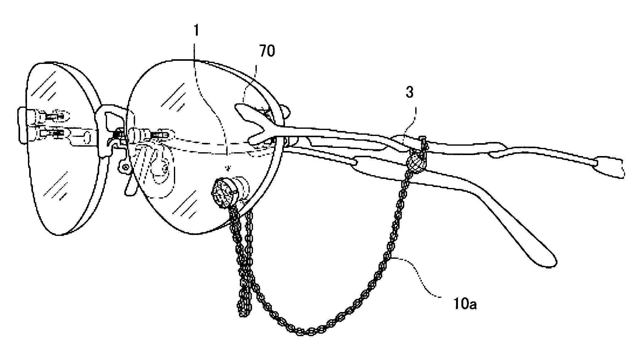
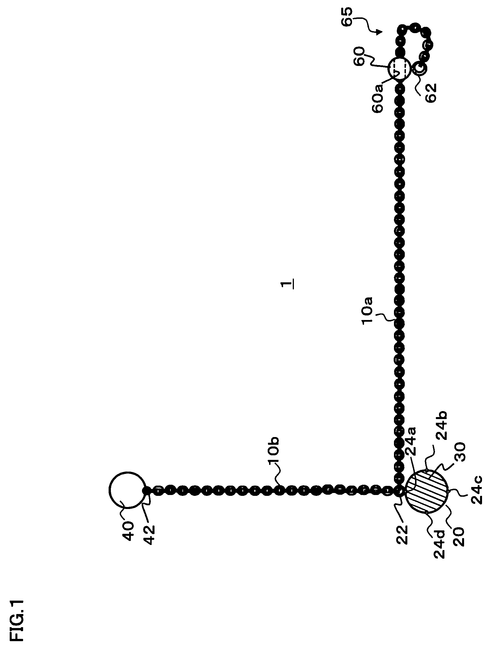
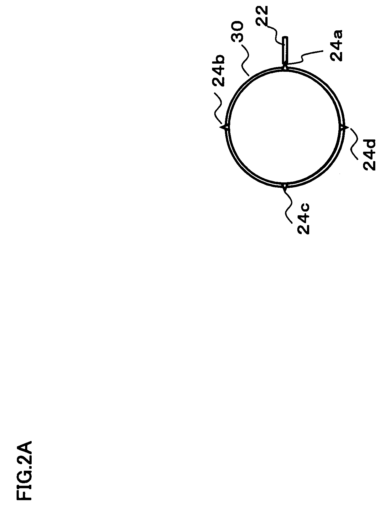
[0032]FIG. 1 illustrates an external figure of the front side of the jewelry article 1 relates to an embodiment of this invention. FIG. 2A illustrates an external figure of a back view of the base 20, and FIG. 2B is a side lateral view of the base 20, on which a main body of a jewel 30 of the jewelry article 1 illustrated in FIG. 1 is fixed. FIG. 2C illustrates a cross sectional structure of the base 20. FIG. 3 illustrates a cross sectional structure in a state of that the jewelry article 1 illustrated in the FIG. 1 is mounted on a lens 70 of the pair of eyeglasses 3.

[0033]As illustrated in FIG. 1, the jewelry article 1 for eyeglasses comprises for example; a chain part 10a and 10b, a base 20, a main body of a jewel 30, a rear surface magnet 40 of a lens of the pair of eyeglasses, and a ball-part for an eyeglass frame.

[0034]Hereupon the chain part 10 and the base 20 are compounded of, for example; gold (Au), silver (Ag), platinum (Pt) or other metals etc.

[0035]Hereupon...

second embodiment

this Invention

[0075]It was illustrated in the first embodiment mentioned above that the base 20 exists among the rear surface magnet 40 and the ball-part 60 for an eyeglass frame, when the ring of an end part of the chain part 10a and 10b are connected to the holdback 22 of the base 20.

[0076]FIG. 6 illustrates an external figure of the front side of the jewelry article 101 relates to the second embodiment of this invention.

[0077]As illustrated in FIG. 6, a ring of end part of the chain part 10a and 10b are connected to the holdback 42 of the rear surface magnet 40 by this jewelry article 101 for eyeglasses. Namely, the rear surface magnet 40 exists among the base 20 and the joining part 65 for an eyeglass frame.

[0078]By the jewelry article 101, as same as the jewelry article 1 for eyeglasses of the first embodiment, the main body of a jewel 30 can be held by a magnetic force generated between the base 20 and the rear surface magnet 40

third embodiment

this Invention

[0079]FIG. 7 illustrates an external figure of the front side of the jewelry article 201 relates to the third embodiment of this invention.

[0080]As illustrated in FIG. 7, an end part of the chain part 10b is connected to the base 20, and another end part of the chain part 10b is jointed to the base 220 by this jewelry article 201 for eyeglasses. The main body of a jewel 230 is mounted on a surface of the base 220.

[0081]Hereupon, a permanent magnet is set on the base 220. Then, a rear surface of the base 20 and 220 are placed on their confronting position on a lens. As a result, the base 20 and 220 are held by a magnetic force generated between them on a fixed position of a lens.

[0082]The jewelry article 201 can achieve the same effect as the first embodiment.

[0083]Moreover, the jewelry article 201 can demonstrate higher ornamental character using the base 220, on which the main body of a jewel 230 is mounted, instead of the rear surface magnet 40 of the first embodimen...


PUM


Abstract

The base, on which the main body of a jewel is mounted, and the rear surface magnet are connected to the chain part. By this jewelry article for eyeglasses being mounted on a lens of the pair of eyeglasses, even if the main body of a jewel and the rear surface magnet fall because of their positioning difference on the lens occurred by some contacts to the main body of the jewel, the base and the rear surface magnet are in a state of being hanged down on an eyeglass frame through the chain part joined to the eyeglass frame by the joining part for an eyeglass frame.

Description

FIELD OF INVENTION[0001]The present invention relates to a jewelry article to be mounted on a lens of eyeglasses.BACKGROUND OF THE INVENTION[0002]In recent years eyeglasses are requested for not only a function but also high ornamental character. Accordingly, for instance; there is a technology to fix a main body of a jewel at any place on a lens by a magnet, as stated in the Japanese published patent application 2000-318395, besides various decorations are given on an eyeglass frame.[0003]This technology is that the first magnet is put on a desired position of a rear surface of a lens by a double-face adhesive tape, and the second magnet, on which an ornamental article is fixed, is held by a magnetic force on a relative position to the first magnet on the front surface of the lens detachable and rotatable.SUMMARY OF THE INVENTION[0004]However, the conventional jewelry for eyeglasses mentioned above has a disadvantage, that the position of the first and the second magnets above ment...

Claims


Application Information

Patent Timeline
Patent Type & Authority Patents(United States)
IPC IPC(8): G02C11/02
CPCG02C7/02G02C11/02G02C2200/02
Inventor DOBASHI, HIDETAKA
Owner CROSSFOR
Why Eureka
Try Eureka