
Luminaire comprising adjustable light modules

a technology of adjustable light modules and luminaires, which is applied in the field of lighting, can solve the problems of generating significant visual clutter, not providing adequate solutions for providing a visually and aesthetically pleasing design, and reducing visual clutter, and achieve the effect of maintaining the spatial profile of the luminair

Active Publication Date: 2010-05-11
SIGNIFY HLDG BV
View PDF29 Cites 85 Cited by
  • Summary
  • Abstract
  • Description
  • Claims
  • Application Information

AI Technical Summary

Benefits of technology

The invention provides a luminaire with adjustable light modules that can pivot within the housing to adjust the direction of the emitted light while maintaining the overall shape of the luminaire. The light modules have a heat sink, a light-emitting element, and an output-optics attachment that maintains a thermal coupling with the heat sink while positioning the optical element in optical alignment with the light-emitting element. Additionally, the invention includes a coupling structure with a base and a longitudinally pivoting light-module coupling portion, along with a linear array of light modules that pivot about a perpendicular transversal axis. The pivotal movement of each light module allows for adjustment of the direction of the luminaire while keeping its shape.

Problems solved by technology

For instance, various currently available light sources provide such adjustments to the directionality and / or shape of an output beam, but do not provide adequate solutions for providing a visually and aesthetically pleasing design that reduces visual clutter.
For example, the result of aiming a row of track heads on a track light may generate significant visual clutter, illustratively described as “Dead Bats” by architects and designers.

Method used


Image

  • Luminaire comprising adjustable light modules
  • Luminaire comprising adjustable light modules
  • Luminaire comprising adjustable light modules

Examples


example 1

[0068]With reference to FIGS. 2 to 6, a luminaire, generally referred to using the numeral 100, and in accordance with one embodiment of the invention, will now be described. The luminaire 100 generally comprises a housing 102 and a linear array of light modules 104 adjustably coupled therein.

[0069]The housing 102 generally provides a coupling structure comprising a base portion 106, which is optionally fixedly or movably mountable to a support structure such as a wall, a ceiling, furniture (e.g., a cabinet, bookshelf, display case, etc.), or the like, and a light module coupling portion 108 pivotally coupled thereto. In general, the luminaire 100 is configured to be mounted horizontally, although one could consider coupling the luminaire 100 vertically, or in another orientation depending on the application for which it is used.

[0070]In this embodiment, the base portion 106 defines a longitudinal structure having attachment tabs 110 extending outwardly from opposed longitudinal end...

example 2

[0077]With reference now to FIGS. 7A to 7F, a luminaire, generally referred to using the numeral 200, and in accordance with another embodiment of the invention, will now be described. The luminaire 200 generally comprises a coupling structure 202 and a linear array of light modules 204 adjustably coupled thereto.

[0078]The coupling structure 202 generally comprises a base portion 206, which is optionally fixedly or movably mountable to a support structure such as a wall, a ceiling, furniture (e.g., a cabinet, bookshelf, display case, etc.), and the like, and a light module coupling portion 208 pivotally coupled thereto. In general, the luminaire 200 is configured to be mounted vertically, although one could consider mounting the luminaire 200 in other orientations depending on the application for which it is used.

[0079]In this embodiment, the light module coupling portion 208, illustratively defined by a substantially longitudinal coupling bar, comprises an attachment tab 212 at a l...

example 3

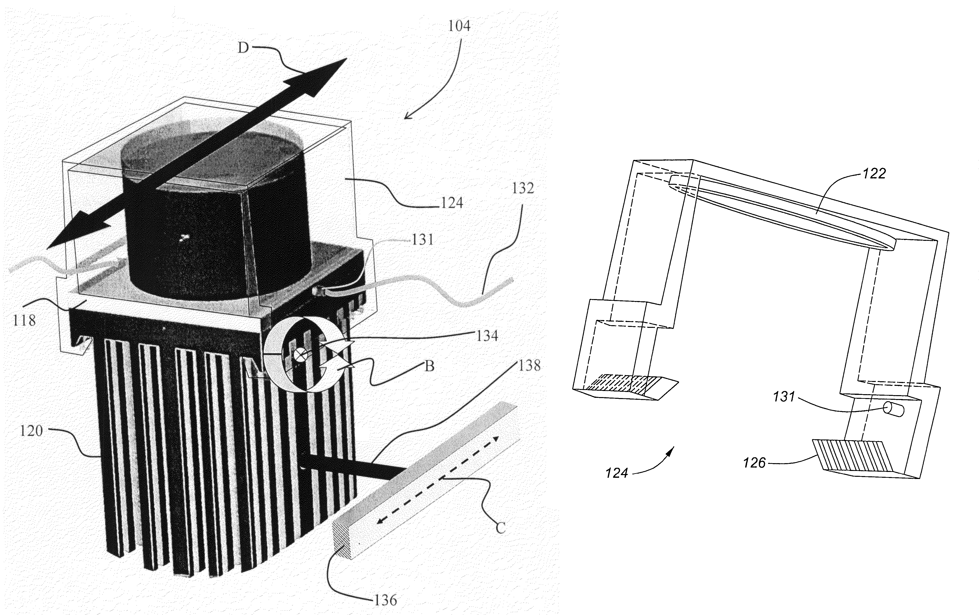
[0087]With reference to FIGS. 8 to 10, a luminaire, generally referred to using the numeral 300, and in accordance with another embodiment of the invention, will now be described. The luminaire 300 generally comprises a housing 302 and a light module 304 adjustably coupled therein.

[0088]The housing 302 generally provides a coupling structure comprising a base portion 306, which is optionally fixedly or movably mountable to a support structure such as a wall, a ceiling, furniture (e.g., a cabinet, bookshelf, display case, etc.), or the like, and a light module coupling portion 308 pivotally coupled thereto.

[0089]In this embodiment, the base portion 306 defines a circular structure having a central rotational coupling (not shown) to the light module coupling portion 308, illustratively defined by substantially parallel coupling tabs configured to pivotally engage the light module 304 via a heatsink 320 thereof.

[0090]The housing 302 further comprises a dome-like structure comprising a ...


PUM


Abstract

The invention provides a general illumination luminaire comprising one or more adjustable light modules. In particular, the luminaire generally comprises one or more light modules, each one of which comprising one or more light-emitting elements, and optionally comprising a heat sink in thermal contact therewith and output optics for managing light output from the one or more light emitting elements. In general, the light modules are adjustably coupled to the luminaire via a coupling structure that provides one or more adjustment mechanisms for adjusting the orientation of the light modules for adjusting an output directionality of the luminaire, while substantially maintaining the spatial profile of the luminaire.

Description

RELATED APPLICATION[0001]This application claims priority to and the benefit of U.S. provisional patent application no. 60 / 822,729, filed on Aug. 17, 2006, the entire disclosure of which is incorporated by reference herein.FIELD OF THE INVENTION[0002]The invention pertains to the field of lighting and in particular to a luminaire comprising adjustable light modules.BACKGROUND[0003]Advances in the development and improvements of the luminous flux of light-emitting devices such as solid-state semiconductor and organic light-emitting diodes (LEDs) have made these devices suitable for use in general illumination applications, including architectural, entertainment, and roadway lighting. Light-emitting diodes are becoming increasingly competitive with light sources such as incandescent, fluorescent, and high-intensity discharge lamps.[0004]One challenge common to all light sources, and particularly to all light sources used in general and specific illumination applications wherein the vi...

Claims


Application Information

Patent Timeline
Patent Type & Authority Patents(United States)
IPC IPC(8): F21V29/00F21V17/00F21V17/06
CPCF21S2/005F21V29/81F21S8/04F21S48/328F21V14/02F21V17/164F21V21/30F21V29/004F21V29/74F21V29/75F21V29/80F21V3/04F21V17/102F21V17/12F21Y2101/02F21S8/033F21Y2115/10F21V29/763F21V29/70F21V19/02F21S45/47
Inventor MATHESON, GEORGE E.
Owner SIGNIFY HLDG BV
Features
  • Generate Ideas
  • Intellectual Property
  • Life Sciences
  • Materials
  • Tech Scout
  • Unparalleled Data Quality
  • Higher Quality Content
  • 60% Fewer Hallucinations
Learn More