
Road vehicle actuated energy device

a technology for actuating energy devices and vehicles, which is applied in the direction of electrical apparatus, dynamo-electric components, dynamo-electric machines, etc., can solve the problems of system failure to be adopted into current roadways, system lack of durability and efficiency,

Inactive Publication Date: 2010-05-11
DAYA ARVIND A
View PDF25 Cites 43 Cited by
  • Summary
  • Abstract
  • Description
  • Claims
  • Application Information

AI Technical Summary

Benefits of technology

[0008]Still another object of the present invention is to provide an improved device for converting the potential energy developed by a moving vehicle into kinetic energy for performing useful work.

Problems solved by technology

To date, such systems have failed to be adopted into current roadways.
It is contemplated that such systems lack necessary durability, efficiency or both and hence have met resistance in adopting the same.

Method used


Image

  • Road vehicle actuated energy device
  • Road vehicle actuated energy device
  • Road vehicle actuated energy device

Examples


Embodiment Construction

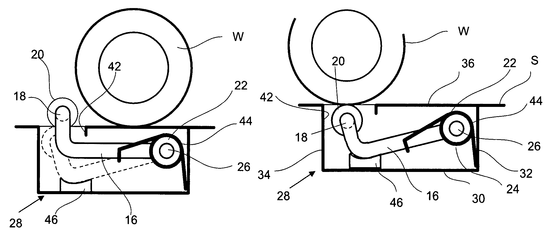
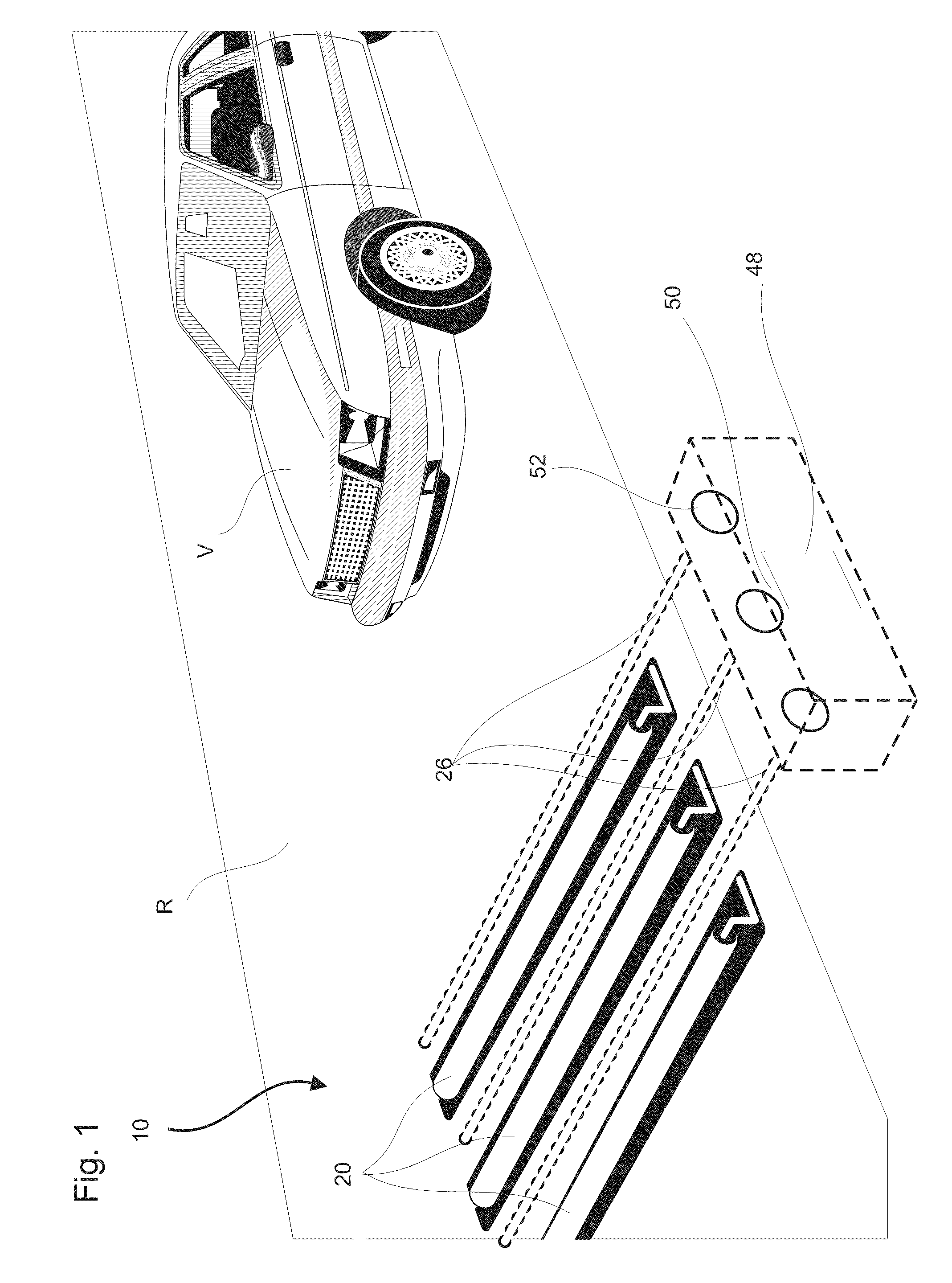
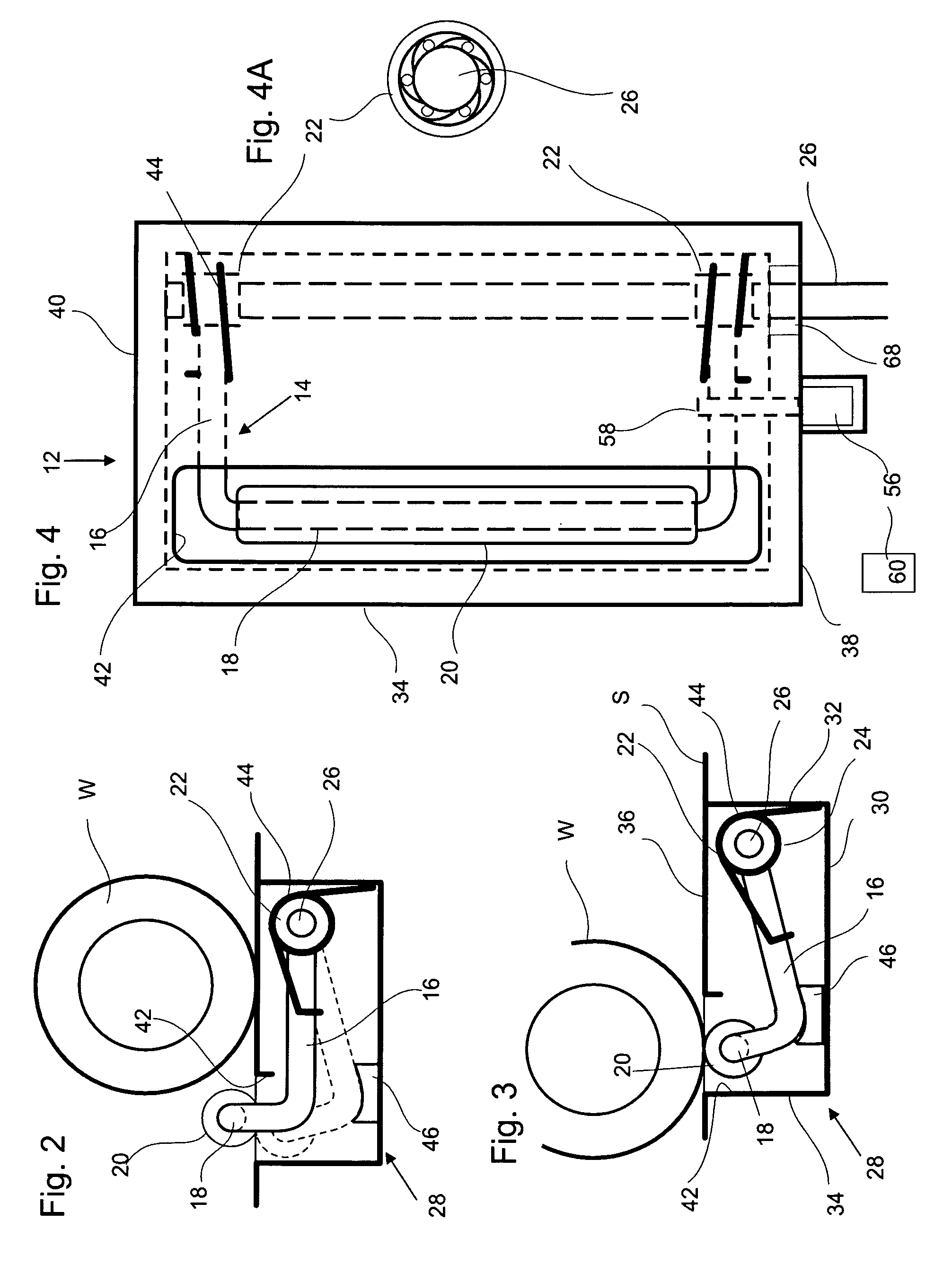
[0021]Referring now to the present invention, the road vehicle actuated energy device is generally designated by the numeral 10. In FIGS. 1-8, there is shown a road R which can have one or more lanes. Operably disposed within road R can be one or more actuators 12 which can be transversely disposed across a path of travel of vehicle V. The actuators 12 can be placed in alignment or offset with respect to one another.

[0022]Each actuator 12 can preferably include a generally U shaped bent member 14 including generally L-shaped sides 16 which are interconnected by a transverse member 18. A roller bearing sleeve 20 can be provided over the transverse member 18. A oneway clutch ring 22 rigidly connects to end 24 of each L-shaped side 16 and has an inner opening configured to receive a drive shaft 26 therethrough and engage drive shaft 26 in a manner to cause one-way rotation thereof when the end 24 is moved from a first (up) position to a second (down) position and freely releases said d...


PUM


Abstract

A road vehicle actuated energy device for use in a path of a vehicle includes an actuator for transverse disposal in a cavity of a road across the path of the vehicle, wherein the actuator includes a bent member having a first end and a second end and when so disposed in the road the first end moves between a first position above the road and a second position below the first position, a rotatable drive shaft, a one-way clutch ring operably connected to the second end of the bent member wherein the one-way clutch ring has an inner opening configured to receive the drive shaft therethrough and engage the drive shaft in a manner to cause one-way rotation thereof when the first end is moved from the first position to the second position and freely releases the drive shaft when moving from the second position to the first position and an energy generator operably connected to the drive shaft in a manner to generate energy upon rotation of the drive shaft.

Description

BACKGROUND OF INVENTION[0001]1. Field of Invention[0002]The present invention relates to capturing otherwise wasted energy to perform usable work and energy conservation. More particularly, the invention relates to an improved system for generating power from the movement of vehicles over a roadway.[0003]2. Related Art[0004]There exist numerous prior devices which have attempted to harness the potential energy contained in moving vehicles. Typically, these devices convert the potential energy into kinetic energy for providing useful work by means of pneumatic and / or mechanical means which can be used to run a generator. To date, such systems have failed to be adopted into current roadways. It is contemplated that such systems lack necessary durability, efficiency or both and hence have met resistance in adopting the same.[0005]Nevertheless, there remains an ever increasing need to conserve energy, particularly in countries where automobiles are the primary mode of transportation. Wh...

Claims


Application Information

Patent Timeline
Patent Type & Authority Patents(United States)
IPC IPC(8): F02B63/04
CPCF03G7/08
Inventor DAYA, ARVIND A.
Owner DAYA ARVIND A
Learn More