High-frequency clock detection circuit
a detection circuit and high-frequency clock technology, applied in the direction of generating/distributing signals, pulse techniques, instruments, etc., can solve the problems of limiting the clock-signal period to be detected, the risk of hacking or theft of data by the accounting terminal, and the inability to detect an attack by a short-time high-frequency clock such as several to several hundred pulses of high-frequency clocks
- Summary
- Abstract
- Description
- Claims
- Application Information
AI Technical Summary
Benefits of technology
Problems solved by technology
Method used
Image

Examples
first embodiment
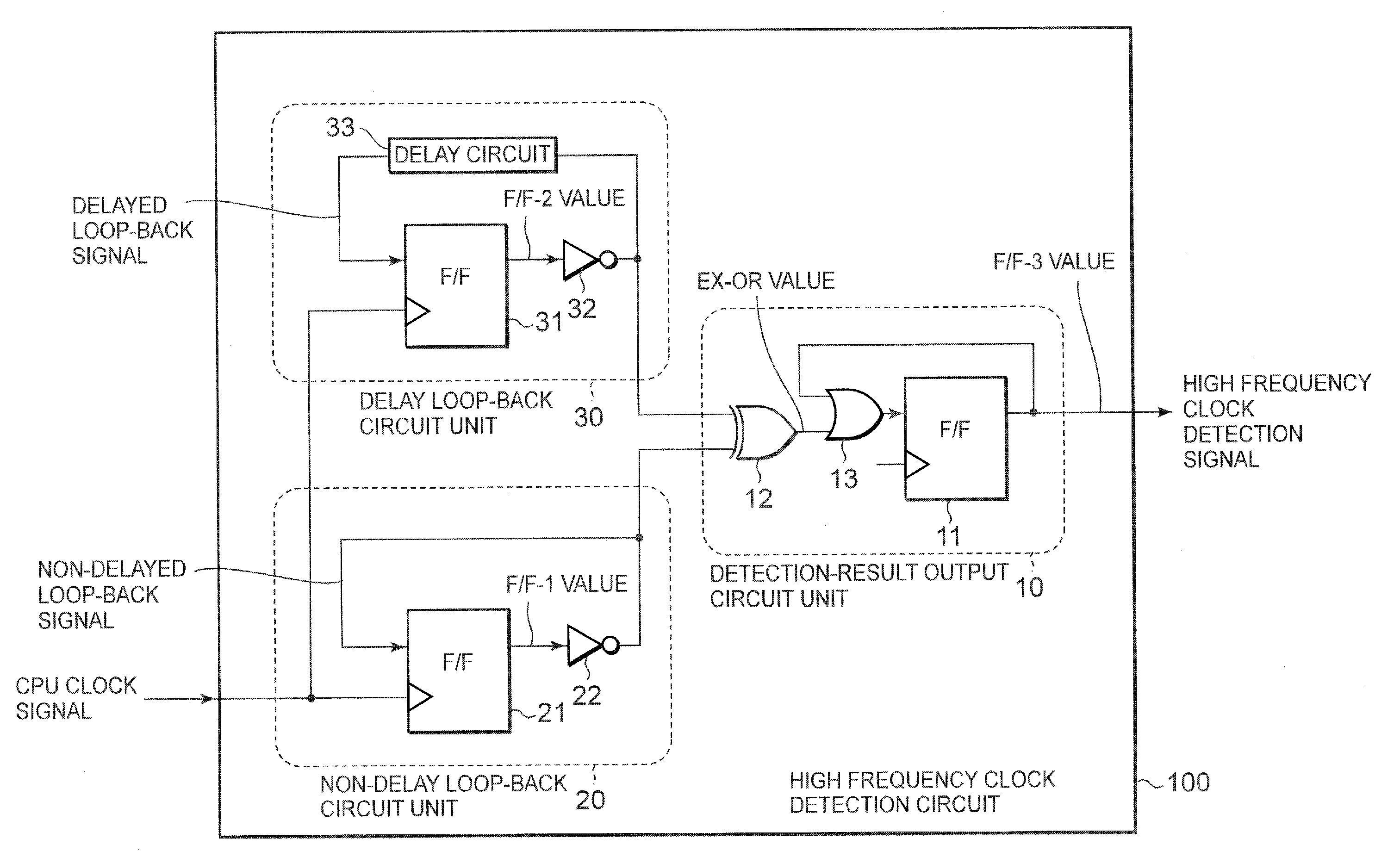
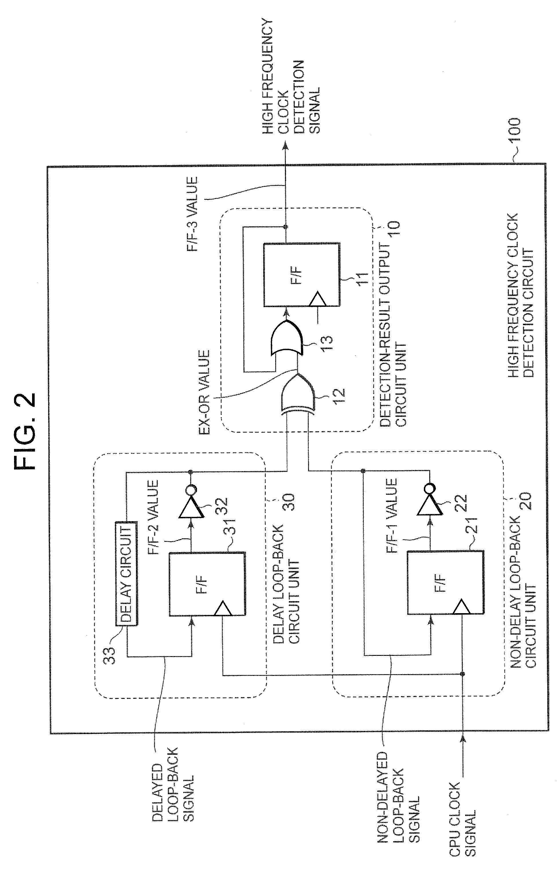
[0020]FIG. 2 is a block diagram of a high-frequency clock detection circuit according to the first embodiment of the invention. A high-frequency clock detection circuit 100 is mainly divided to the main three circuit units, and has a configuration that a non-delay loop-back circuit 20, a delay loop-back circuit 30, and a detection-result output circuit 10 are included.
[0021]The non-delay loop-back circuit 20 includes a D (delay)-type flip-flop circuit 21 and an inverting circuit 22, so that the output signal (F / F-1 value) of the flip-flop circuit 21 is inverted by the inverting circuit 22 and the inverted signal is feedback inputted to the flip-flop circuit 21 by directly loop-backing as a non-delayed loop-back signal.
[0022]A delay loop-back circuit 30 includes a D-type flip-flop circuit 31, an inverting circuit 32, and a delay circuit 33, so that the output signal (F / F-2 value) of the flip-flop circuit 31 is inverted by the inverting circuit 32 and the inverted signal is feedback i...
second embodiment
[0036]FIG. 5 is a block diagram of a high frequency detection circuit according to the second embodiment. The high frequency clock detection circuit 100 consists of the non-delay loop-back circuit 20, the delayed loop-back circuit 30, and the detection-result output circuit 10. The non-delay loop-back circuit 20, and the delayed loop-back circuit 30 have the same configuration as in the first embodiment.
[0037]According to the second embodiment, the configuration of the detection-result output circuit unit 10 is different from the one of the first embodiment. The detection-result output circuit unit 10 includes a logic exclusive-OR circuit 12 and a counter 14 realized by a plurality of flip-flop circuits. The logic exclusive-OR circuit 12 provides the counter 14 with the logic exclusive-OR value (EX-OR value) between the inverted signal from the non-delay loop-back circuit 20 and the inverted signal from the delay loop-back circuit 30. The counter 14 counts states where the logic exc...
third embodiment
[0042]FIG. 7 is a block diagram of a high frequency detection circuit according to the third embodiment. The high frequency clock detection circuit 100 is composed by the non-delay loop-back circuit unit 20, the delayed loop-back circuit unit 30, and the detection-result output circuit 10, and further includes a count threshold setting register 41 and a bus interface 42. The non-delay loop-back circuit unit 20 and the delay loop-back circuit unit 30 have the same configurations as in the first and the second embodiments.
[0043]The detection-result output circuit unit 10 according to the third embodiment includes a function to change the count threshold referring to the content of the count threshold register 41, in addition to the configuration according to the second embodiment. The content of the count threshold register 41 is set by executing the software in the control circuit (cf. FIG. 2) through the bus interface. The counter 14 outputs the high frequency clock detection signal...
PUM
 Abstract
Description
Claims
Application Information
 - R&D
- Intellectual Property
- Life Sciences
- Materials
- Tech Scout
- Unparalleled Data Quality
- Higher Quality Content
- 60% Fewer Hallucinations
Browse by: Latest US Patents, China's latest patents, Technical Efficacy Thesaurus, Application Domain, Technology Topic, Popular Technical Reports.
© 2025 PatSnap. All rights reserved.Legal|Privacy policy|Modern Slavery Act Transparency Statement|Sitemap|About US| Contact US: help@patsnap.com