System and method for managing consumption of power supplied by an electric utility

a technology of power consumption and control system, applied in the direction of mechanical power/torque control, resistance welding apparatus, electric devices, etc., can solve the problems of high inefficiency of the system for measuring the actual load shed to the serving utility, lack of unique attributes of prior art, and insufficient security of the load accuracy of the controlled devi

Active Publication Date: 2010-05-11
LANDISGYR TECH INC
View PDF65 Cites 347 Cited by
  • Summary
  • Abstract
  • Description
  • Claims
  • Application Information

AI Technical Summary

Benefits of technology

[0027]One of the most beneficial advantages of an IP-based power management system, as provided in one embodiment of the present invention, is accurate reporting of the actual amount of power saved by each customer on an individual basis. Embodiments of the present invention monitor and calculate precisely how many kilowatts (or carbon credits) are being generated or saved per customer instead of merely providing an estimate. Furthermore, embodiments of the present invention provide means for tracking the actual amount of deferred load and pollutants according to generation mix, serving utility and geographic area.

Problems solved by technology

While tele-metering has been used for the express purpose of reporting energy usage, no techniques exist for calculating power consumption, carbon gas emissions, sulfur dioxide (SO2) gas emissions, and / or nitrogen dioxide (NO2) emissions, and reporting the state of a particular device under the control of a two-way positive control load management device.
While one-way devices are generally industry standard and relatively inexpensive to implement, the lack of a return path from the receiver, combined with the lack of information on the actual devices connected to the receiver, make the system highly inefficient for measuring the actual load shed to the serving utility.
While initially this prior art generally describes a system that would assist utilities in managing power load control, the prior art does not contain the unique attributes necessary to construct or implement a complete system.
In particular, this patent is deficient in the areas of security, load accuracy of a controlled device, and methods disclosing how a customer utilizing applicable hardware might set parameters, such as temperature set points, customer preference information, and customer overrides, within an intelligent algorithm that reduces the probability of customer dissatisfaction and service cancellation or churn.
However, until recently, technologies such as smart breakers and command relay devices were not considered for use in residential and commercial environments primarily due to high cost entry points, lack of customer demand, and the cost of power generation relative to the cost of implementing load control.
While the disclosed OPP does provide some intelligence in the power management system, it does not determine which end devices under its control to turn-off during a power reduction event, instead relying on the host device to make such decision.
However, neither the host processor nor the OPP determine which loads to remove in order to satisfy a power reduction command from an electric utility, particularly when the command is issued by one of several utilities under the management of a power management system.
Further, neither the host processor nor the OPP tracks or accumulates power saved and / or carbon credits earned on a per customer or per utility basis for future use by the utility and / or customer.
Still further, the system of this publication lacks a reward incentive program to customers based on their participation in the power management system.
Still further, the system described in this publication does not provide for secure communications between the host processor and the OPP, and / or between the OPP and the end device.
As a result, the described system lacks many features that may be necessary for a commercially viable implementation.

Method used


Image

  • System and method for managing consumption of power supplied by an electric utility
  • System and method for managing consumption of power supplied by an electric utility
  • System and method for managing consumption of power supplied by an electric utility

Examples


Embodiment Construction

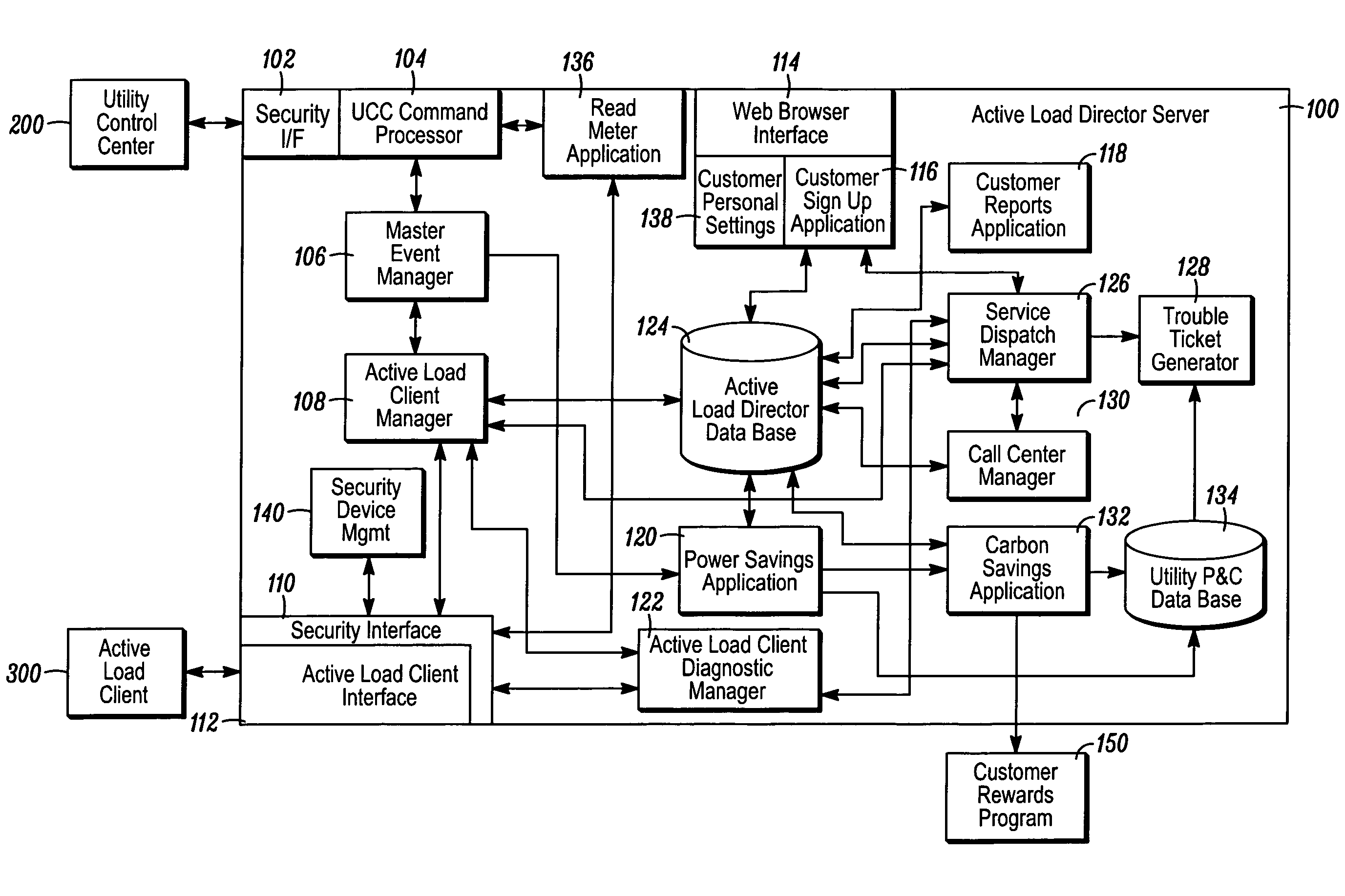
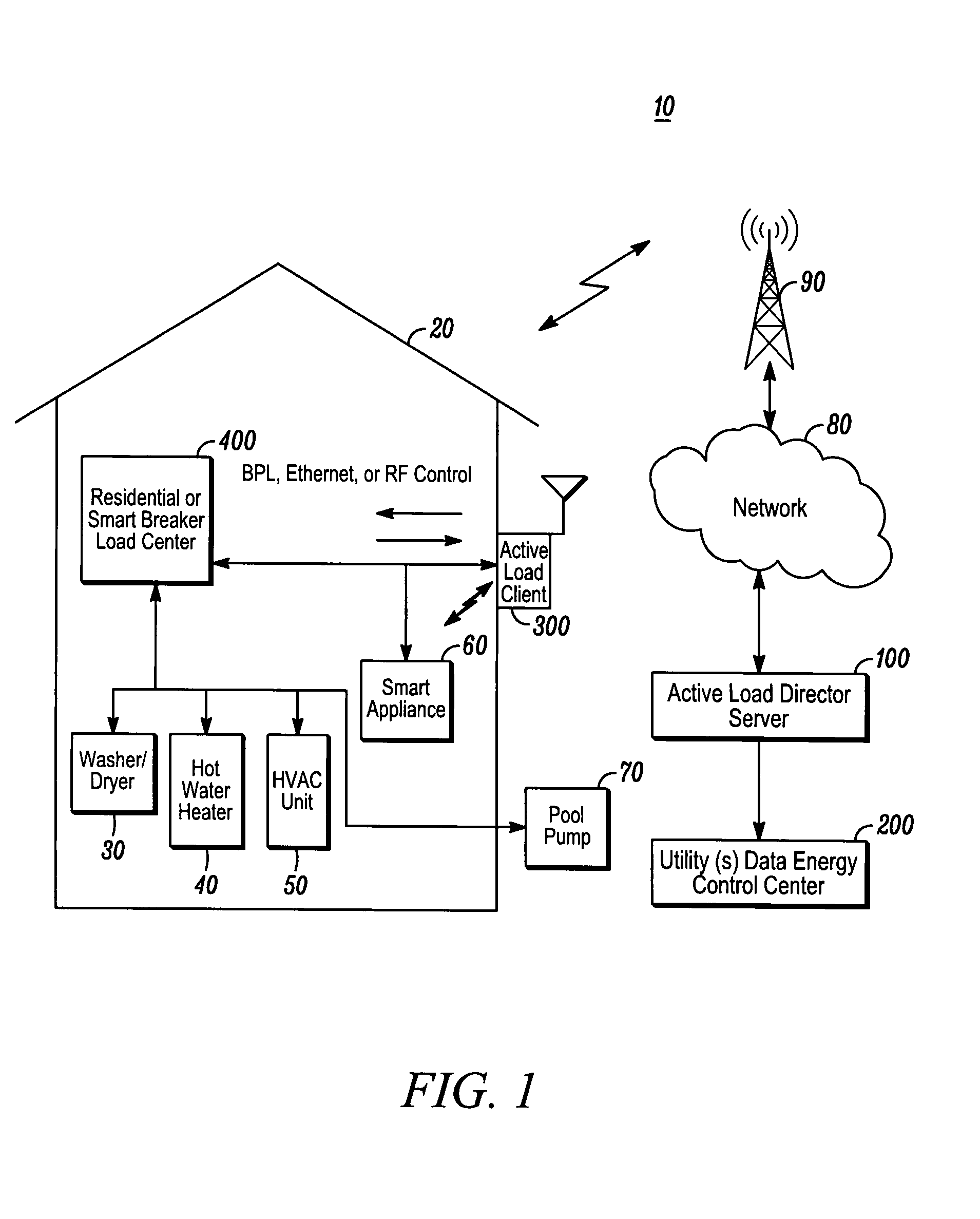
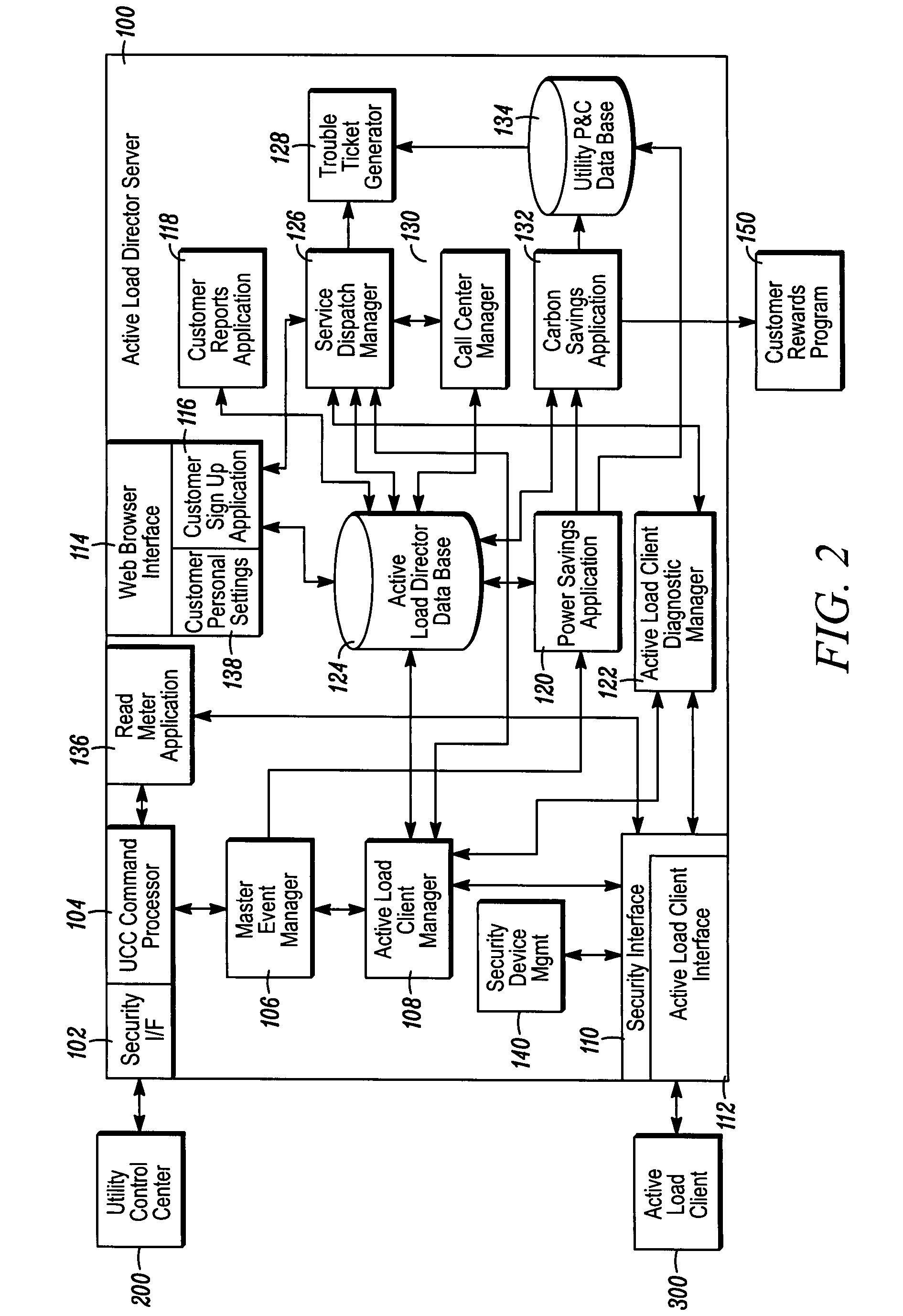
[0021]Before describing in detail exemplary embodiments that are in accordance with the present invention, it should be observed that the embodiments reside primarily in combinations of apparatus components and processing steps related to actively managing power loading on an individual subscriber basis and optionally tracking power savings incurred by both individual subscribers and an electric utility. Accordingly, the apparatus and method components have been represented where appropriate by conventional symbols in the drawings, showing only those specific details that are pertinent to understanding the embodiments of the present invention so as not to obscure the disclosure with details that will be readily apparent to those of ordinary skill in the art having the benefit of the description herein.

[0022]In this document, relational terms, such as “first” and “second,”“top” and “bottom,” and the like, may be used solely to distinguish one entity or element from another entity or ...


PUM

PropertyMeasurementUnit
electric poweraaaaaaaaaa
electric utilityaaaaaaaaaa
poweraaaaaaaaaa

Abstract

A system for managing consumption of power supplied by an electric utility to power consuming devices includes at least one client device and a server. Each client device operates at least partially responsive to control messages received from the server and controls operation of one or more controllable devices. Each controllable device selectively enables and disables a flow of power to one or more of the consuming devices. The server stores information, on a per client device basis, relating to power consumed by the consuming devices. When a power reduction is requested by the utility, the server selects, based on client device information stored in the database, at least one client device to which to issue a power reduction message that indicates at least one of an amount of power to be reduced and an identification of a controllable device to be instructed to disable a flow of power.

Description

BACKGROUND OF THE INVENTION[0001]1. Field of the Invention[0002]The present invention relates generally to the field of electrical power load control systems and more particularly to a method and system for actively controlling power load management for individual customers and optionally tracking power savings for both the individual customer as well as the overall electric utility.[0003]2. Description of Related Art[0004]The increased awareness of the impact of carbon emissions from the use of fossil fueled electric generation combined with the increased cost of producing peak power during high load conditions has increased the need for alternative solutions utilizing load control as a mechanism to defer, or in some cases eliminate, the need for the deployment of additional generation capacity by electric utilities. Existing electric utilities are pressed for methods to defer or eliminate the need for construction of fossil-based electricity generation. Today, a patchwork of syste...

Claims


Application Information

Patent Timeline
Patent Type & Authority Patents(United States)
IPC IPC(8): G05D3/12G05D11/00G05D17/00G05D9/00G05D5/00G01R21/00G05F3/00G05F3/02G05F5/00G01R21/06G06Q10/00
CPCG01D4/004G06Q10/06393G06Q30/0207G06Q50/06H02J3/14G06Q10/06Y04S20/242Y02B70/3225Y02B90/242Y02B90/245Y02B70/343Y04S20/222Y04S20/224Y04S20/322Y04S20/34Y04S20/40Y04S50/14H02J2003/143Y02B70/3266H02J2310/14Y02B70/34Y04S20/30G01D2204/14G06Q50/26Y02B70/30Y02B90/20
Inventor FORBES, JR., JOSEPH W.WEBB, JOEL L.
Owner LANDISGYR TECH INC
Why Eureka
Try Eureka