Harvesting machine combination for the utilization of plant remains

a technology of plant remains and harvesting machines, which is applied in the field of harvesting machine combinations for the utilization of plant remains, can solve the problems of requiring energy from the internal combustion engine of the combine, contaminated soil particles, and insufficient quantity, so as to achieve the effect of not fatigueing the operator

Active Publication Date: 2010-05-25
DEERE & CO
View PDF15 Cites 29 Cited by
  • Summary
  • Abstract
  • Description
  • Claims
  • Application Information

AI Technical Summary

Benefits of technology

[0007]In this way, the harvested crop remains from the combine are chopped to a desired size and deposited in a container. Due to the automatic steering and the speed input from the forage harvester, it follows the combine without any input from the operator, an operation is possible that does not fatigue the operator.

Problems solved by technology

The deposit of the harvested crop remains on the ground and the subsequent take-up by means of a baler or a forage harvester has the disadvantage that the harvested crop remains can be contaminated by particles on the ground.
The blowers attached to the combine avoid this problem (U.S. Pat. No. 3,669,123 A and SU 376 054 A), but require energy from the internal combustion engine of the combine, which is not always available in a sufficient quantity.
The chassis that are separately towed behind the combine with internal combustion engines and blowers are not subject to the same disadvantage, but they are rather cumbersome during operation of the combine on public roads, since they must in addition transport the cutter head of the combine, which, as a rule, is drawn along behind the combine on a trailer, which requires a separate tractor and operator.
A further disadvantage of the chassis with internal combustion engine and blowers lies in the fact that no means are provided for the reduction of the harvested crop remains, which has shown itself to be particularly disadvantageous if they are to be used to produce bio-energy.

Method used


Image

  • Harvesting machine combination for the utilization of plant remains
  • Harvesting machine combination for the utilization of plant remains

Examples


Embodiment Construction

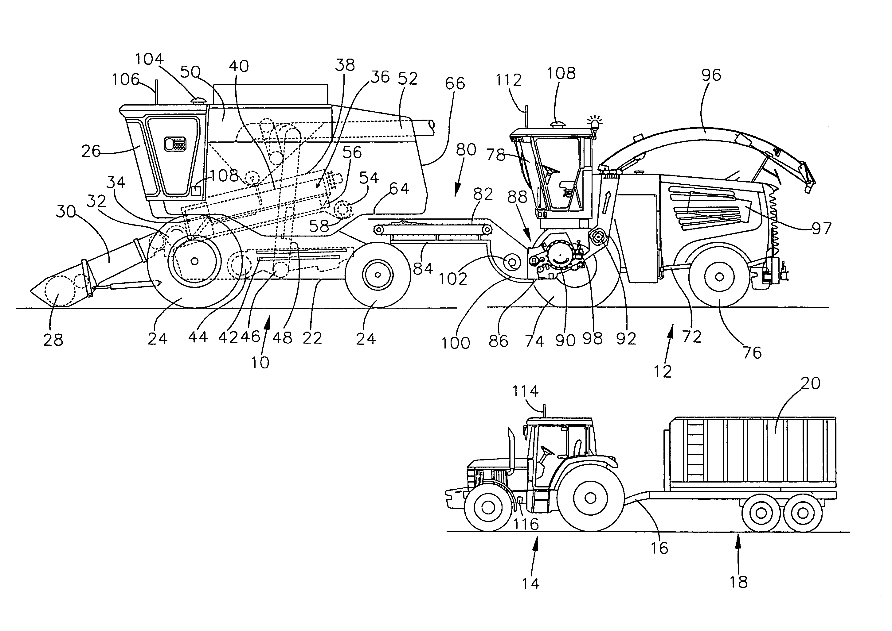
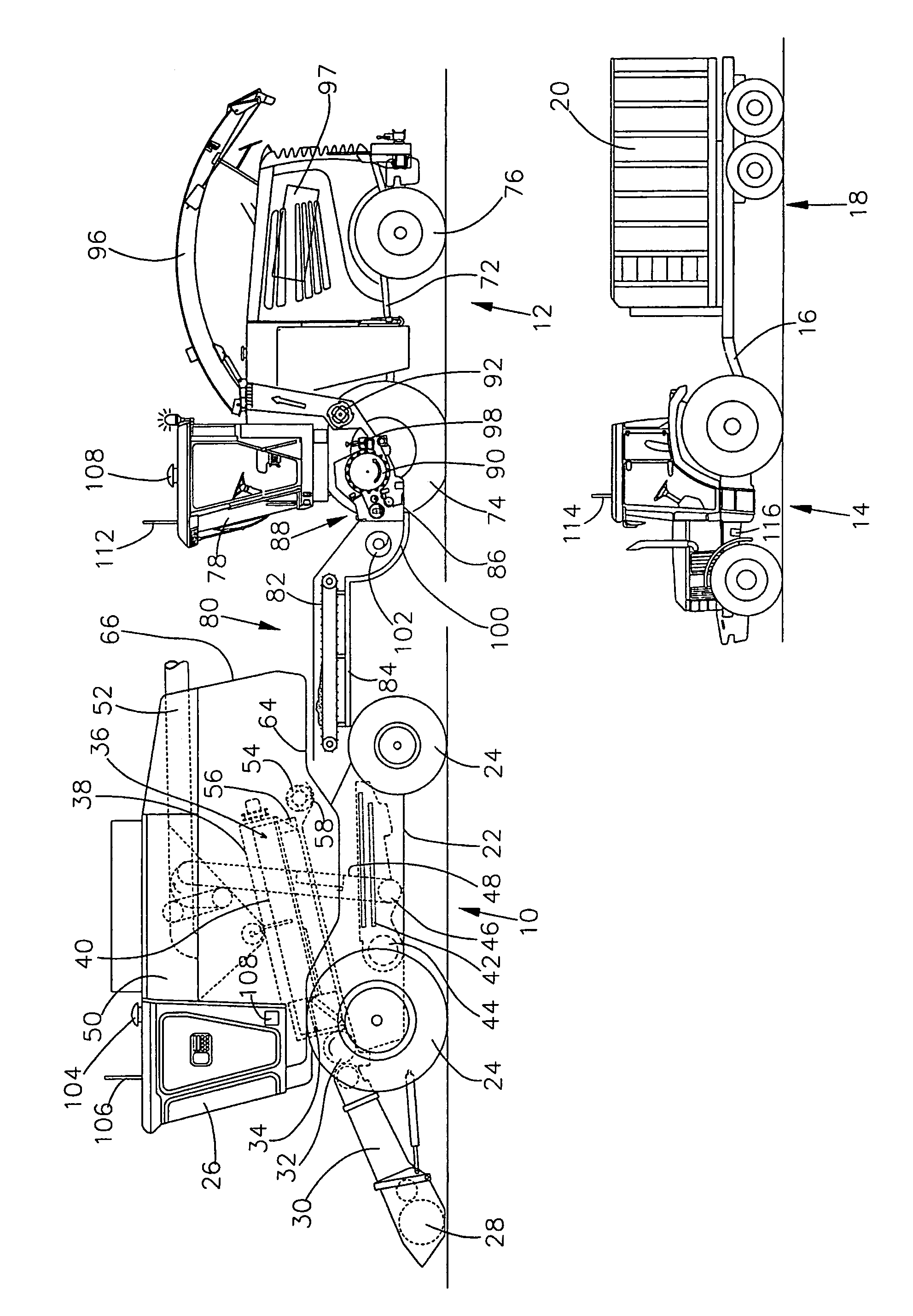
[0011]The drawing FIGURE schematically shows a harvesting machine combination for the harvest of kernel type crops that permits the utilization not only of the kernels but also of the plant remains. The harvesting machine combination includes a self propelled combine 10, a self propelled forage harvester 12, a self propelled tractor 14 and a trailer 18 that includes a container 20 and is towed by the tractor 14 by means of a tow bar 16.

[0012]The self-propelled combine 10 includes a chassis 22 with wheels 24 in engagement with the ground that are fastened to the chassis 22 and are used for the propulsion of the combine 10 in a forward operating direction, that shown in the drawing FIGURE towards the left. The operation of the combine 10 is controlled from an operator's cab 26. A cutter head 28, that can be replaced during the harvest of corn by a corn picker, is used to harvest crop containing corn and to conduct it to a slope conveyor 30. The harvested crop is conducted by the slope...


PUM


Abstract

A harvesting machine combination for the utilization of harvested plant remains is provided and includes a combine with an outlet for harvested crop remains, a self propelled forage harvester that includes a conveyor to take over the harvested crop remains from the outlet of the combine, a discharge arrangement for the harvested crop remains, an engine for the drive of the conveyor and a container to take up the harvested crop remains delivered by the discharge arrangement. The combine is equipped with a transmitting arrangement for the transmission of position data and / or operation direction and speed data of the combine. The forage harvester is equipped with a receiving arrangement that interacts with an automatic steering and speed input arrangement of the forage harvester that can be operated on the basis of the data received by the receiving arrangement in order to permit the forage harvester to follow the combine automatically.

Description

FIELD OF THE INVENTION[0001]The invention concerns a harvesting machine combination for the utilization of plant remains. The combination includes a combine with an outlet for plant remains, a transfer arrangement having a chassis, a conveyor for the takeover of the harvested crop remains from the outlet of the combine, a discharge arrangement for the harvested crop remains and a motor to drive the conveyor, and a container to take up the harvested crop remains delivered by the discharge arrangement.BACKGROUND OF THE INVENTION[0002]During harvesting of cereal crops, corn or other kernel-producing plants by means of a combine, further plant materials are produced in addition to the clean crop, such as chaff and straw. These plant components, characterized herein as plant remains are, as a rule, deposited on the ground in the state of the art in order to take them up subsequently with a baler or a forage harvester (DE 1 096 667 A) or they are chopped by means of a straw chopper and di...

Claims


Application Information

Patent Timeline
Patent Type & Authority Patents(United States)
IPC IPC(8): A01B69/00
CPCA01D41/12A01D43/08A01D43/07A01D43/063
Inventor WENDLING, IGNATZ
Owner DEERE & CO
Why Eureka
Try Eureka