Combined subway wall and door assembly and associated method

a technology of subway wall and door assembly, applied in the direction of refuge islands, roads, constructions, etc., can solve the problems of invariably dying, many individuals are injured or killed, and the subway is inherently dangerous

Inactive Publication Date: 2010-05-25
LHB ENTERPRISE CORP
View PDF7 Cites 33 Cited by
  • Summary
  • Abstract
  • Description
  • Claims
  • Application Information

AI Technical Summary

Benefits of technology

[0017]The automatic biasing mechanism further includes a control switch electrically coupled to the logic gate and responsive to the output signal. Such a control switch generates and transmits first and second control signals for toggling the light-emitting members between first and second colors when the logic gate output signal is true and false respectively. The control signal further generates and transmits a third control signal upon receipt of the true output signal from the logic gate. An actuator assembly is operably coupled directly to the control switch and the access ports respectively. Such an actuator assembly conveniently causes the access doors to slidably adapt between the open and closed positions when the control switch generates and transmits the third control signal.
[0018]The actuator assembly includes a single and unitary bracket extending upwardly from the first plurality of support members up to a termination point located above the second plurality of support members respectively. A plurality of guide tracks is directly anchored to respective top portions of the brackets and is registered parallel to the first and second pluralities of support members respectively. A plurality of casters is rotatably connected to the guide tracks and extends downwardly therefrom such that the casters become directly abutted against top edges of the access doors respectively. Such casters advantageously rotate along clockwise and counter clockwise directions when the control switch transmits the third control signal and thereby cause the access doors to linearly travel along lateral and medial directions within respect to the brackets respectively.

Problems solved by technology

Although subways provide millions of individuals with an affordable and efficient way to commute, subways are inherently dangerous and many individuals are injured or killed each year.
Most accidents result from individuals accidentally falling or intentionally jumping onto the rails, ahead of an oncoming subway.
Although a few individuals survive, death is invariably the result of jumping in front of a fast-moving subway train, hurtling into the subway station at nearly 40 mph.
Unfortunately, this prior art example does not prevent the specific dangers associated with subway platforms.
Unfortunately, this prior art example does not automatically biased to an open position when it becomes appropriate for a user to enter the blocked opening.
Unfortunately, this prior art example does not prevent the specific dangers associated with subway platforms.

Method used


Image

  • Combined subway wall and door assembly and associated method
  • Combined subway wall and door assembly and associated method
  • Combined subway wall and door assembly and associated method

Examples


Embodiment Construction

[0035]The present invention will now be described more fully hereinafter with reference to the accompanying drawings, in which a preferred embodiment of the invention is shown. This invention may, however, be embodied in many different forms and should not be construed as limited to the embodiment set forth herein. Rather, this embodiment is provided so that this application will be thorough and complete, and will fully convey the true scope of the invention to those skilled in the art. Like numbers refer to like elements throughout the figures.

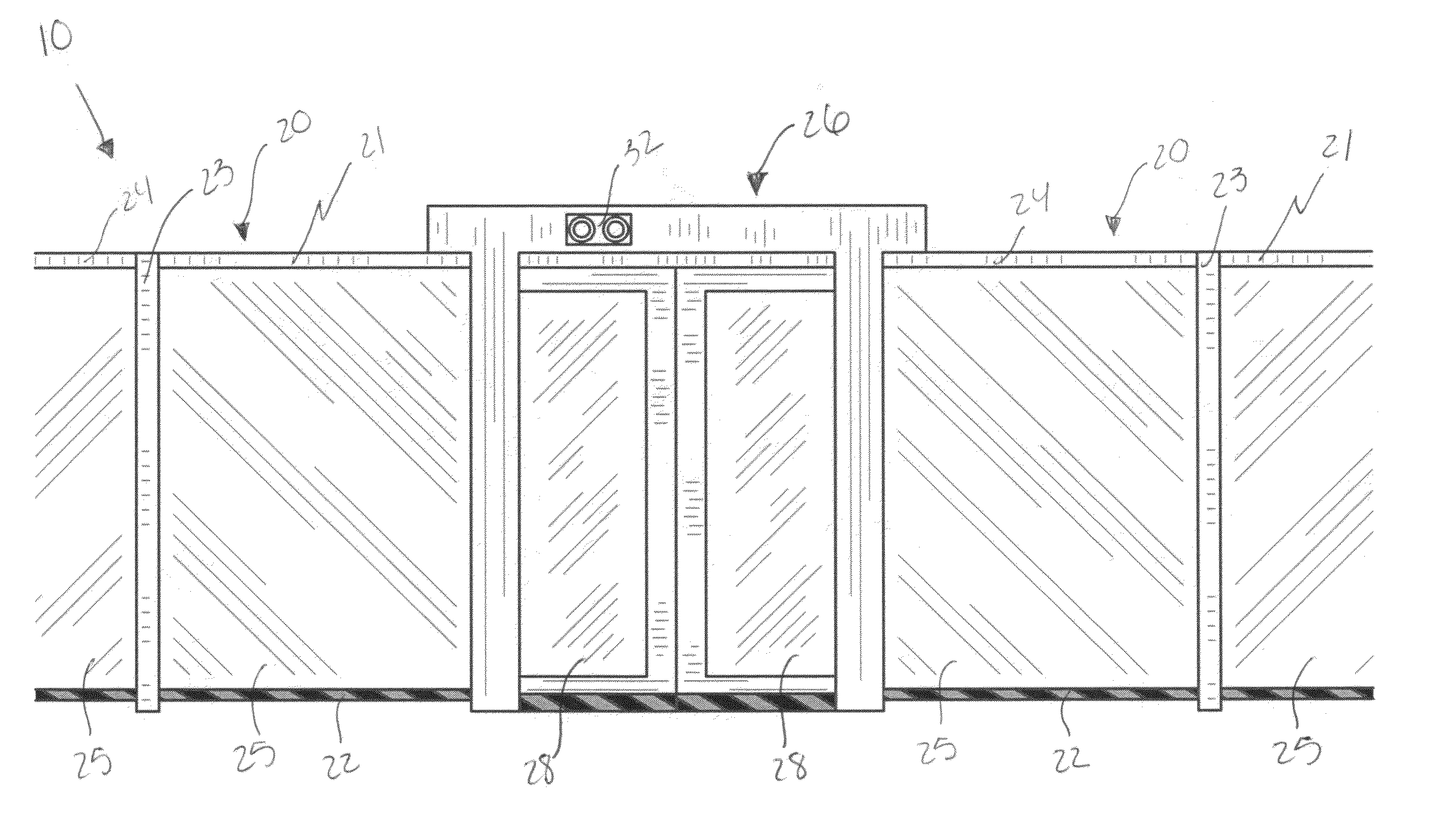
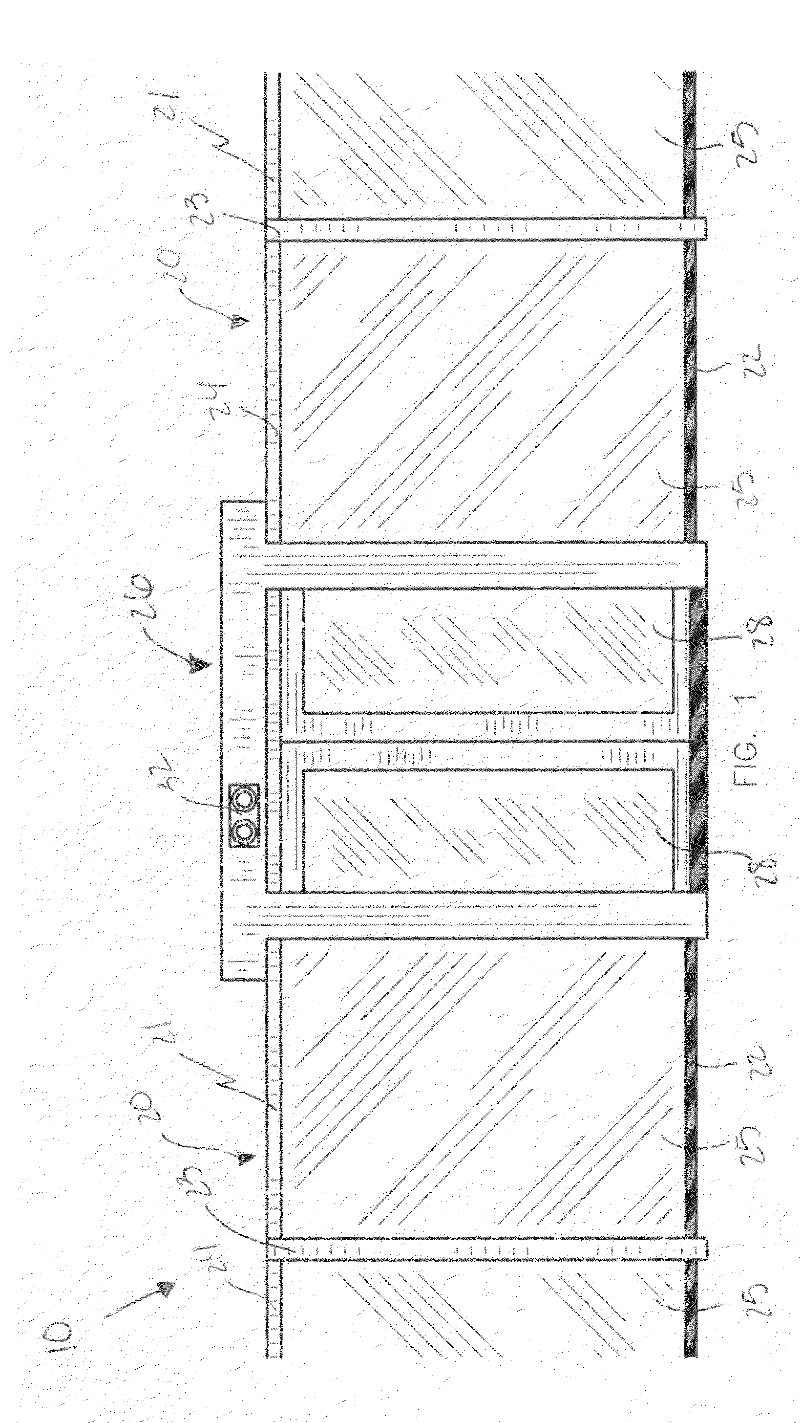
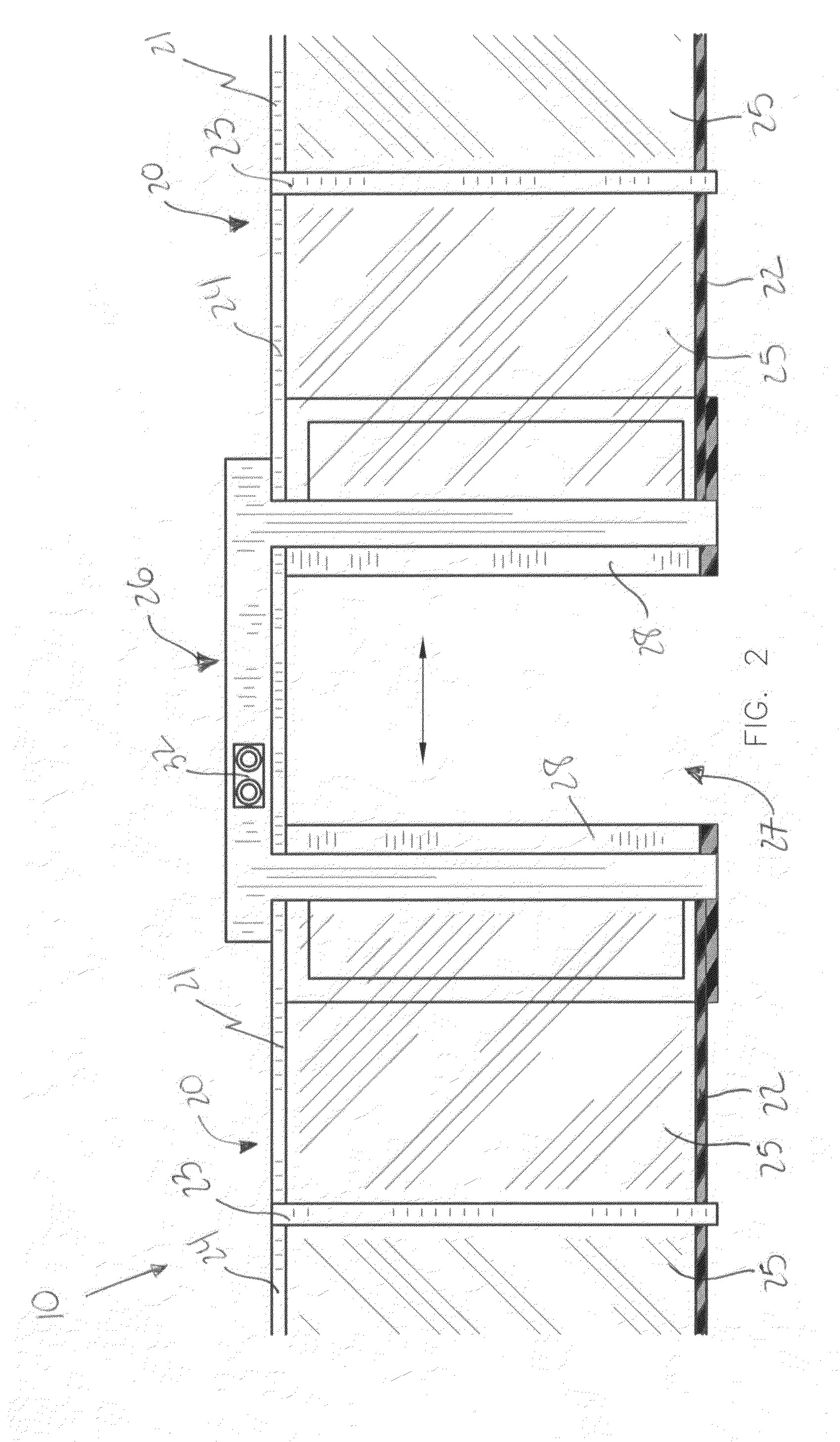
[0036]The assembly of this invention is referred to generally in FIGS. 1-7 by the reference numeral 10 and is intended to protect a combined subway wall and door assembly. It should be understood that the assembly 10 may be used to protect many different types of platforms and should not be limited in use with only those types of platforms mentioned herein.

[0037]Referring initially to FIGS. 1, 2, 3, 4, 5 and 6, a combined wall and door assemb...


PUM


Abstract

A combined wall and door assembly includes a static wall assembly including a segmented support frame with a rectilinear shape. The static wall assembly further includes a plurality of transparent fiberglass panels directly coupled to the support frame and spaced along an entire longitudinal length of the support frame. The assembly further includes a mechanism for automatically biasing the access doors between open and closed positions when the subway train arrives and leaves a train terminal respectively such that passengers are prohibited from premature ingress and egress of the subway train during a schedule stop.

Description

CROSS REFERENCE TO RELATED APPLICATIONS[0001]This application claims the benefit of U.S. Provisional Application No. 60 / 850,821, filed Oct. 12, 2006, the entire disclosures of which are incorporated herein by reference.STATEMENT REGARDING FEDERALLY SPONSORED RESEARCH OR DEVELOPMENT[0002]Not Applicable.REFERENCE TO A MICROFICHE APPENDIX[0003]Not Applicable.BACKGROUND OF THE INVENTION[0004]1. Technical Field[0005]This invention relates to subway door assemblies and, more particularly, to a combined subway wall and door assembly for providing a safe passageway to ingress and egress a subway train from an adjacent platform.[0006]2. Prior Art[0007]The first subway, which began operating in 1863 in London, England, used steam locomotives. The subway was successful and it expanded, converting to electricity in about 1896. The first electric subway line in the United States opened in Boston, Mass., in 1897 to immediate success. New York City followed in 1904 with approximately nine miles of...

Claims


Application Information

Patent Timeline
Patent Type & Authority Patents(United States)
IPC IPC(8): B61B1/00B61B1/02
CPCB61B1/02
Inventor BURGESS, LAMASS
Owner LHB ENTERPRISE CORP
Why Eureka
Try Eureka