Dehider with governor and strengthened blade

a dehider and governor technology, applied in the field of dehiders, can solve the problems of excessive speed under no-load condition, increased tool wear and noise, and design of oscillating disk blades

Active Publication Date: 2010-05-25
JARVIS PROD
View PDF5 Cites 14 Cited by
  • Summary
  • Abstract
  • Description
  • Claims
  • Application Information

AI Technical Summary

Benefits of technology

[0020]In one aspect of the invention, the speed governor is connected to spin with the pneumatic motor and operates by centrifugal force to restrict the flow of pressurized air from the air inlet to the pneumatic motor to decrease the speed of the motor when the motor speed is above the desired rotational speed.
[0021]In the preferred embodiment, the speed governor includes a valve head connected to spin with the pneumatic motor and the air inlet is connected to a valve seat. The valve head moves towards the valve seat to restrict the flow of pressurized air from the air inlet to the pneumatic motor and decrease the speed of the motor when the motor speed is above the desired rotational speed.
[0022]In another aspect of the invention, the speed governor includes a governor spring biasing the valve head away from the valve seat and a movable mass connected to spin with the pneumatic motor. The movable mass moves outward as the speed governor spins and compresses the governor spring to move the valve head towards the valve seat and restrict the flow of pressurized air from the air inlet to the pneumatic motor.

Problems solved by technology

Although this dehider design has proven effective, existing designs tend to slow down under a heavy cutting load and then return to a higher speed as the cutting load is removed.
This higher no-load speed produces undesirable increases in tool wear and noise.
The excess speed under the no-load condition is particularly problematical for a dehider having oscillating blades due to the frequent forward and back reversals of the blades and pushrods and the wear associated with the oscillating motion at high speed.
Another problem in existing designs lies in the design of the oscillating disk blades.
The limited size of the bearing center hole produces wear at a greater rate than is desirable.
As the blade wears, the center hole enlarges until the blade eventually becomes unusable.
Often, it is this center bearing wear that limits the useful life of the blade.
Still another problem lies in the oscillating nature of the eccentric-driven pushrods and blades, which produces substantial vibration.
A known method of reducing this vibration is to use a counterbalance mass on the main drive gear, however, this solution is only partly effective.
Initially, the magnitude of this wobbling motion is quite limited and the tool can be used comfortably for long periods of time.
However, over time, the wobbling motion produces significant excess wear.
As the bearings and moving parts begin to wear, the wobble increases in amplitude until it produces an extremely objectionable vibration.
Moreover, the wear produced by this motion shortens the lifetime of the component parts in the tool.

Method used


Image

  • Dehider with governor and strengthened blade
  • Dehider with governor and strengthened blade
  • Dehider with governor and strengthened blade

Examples


Embodiment Construction

)

[0039]In describing the preferred embodiment of the present invention, reference will be made herein to FIGS. 1-10 of the drawings in which like numerals refer to like features of the invention.

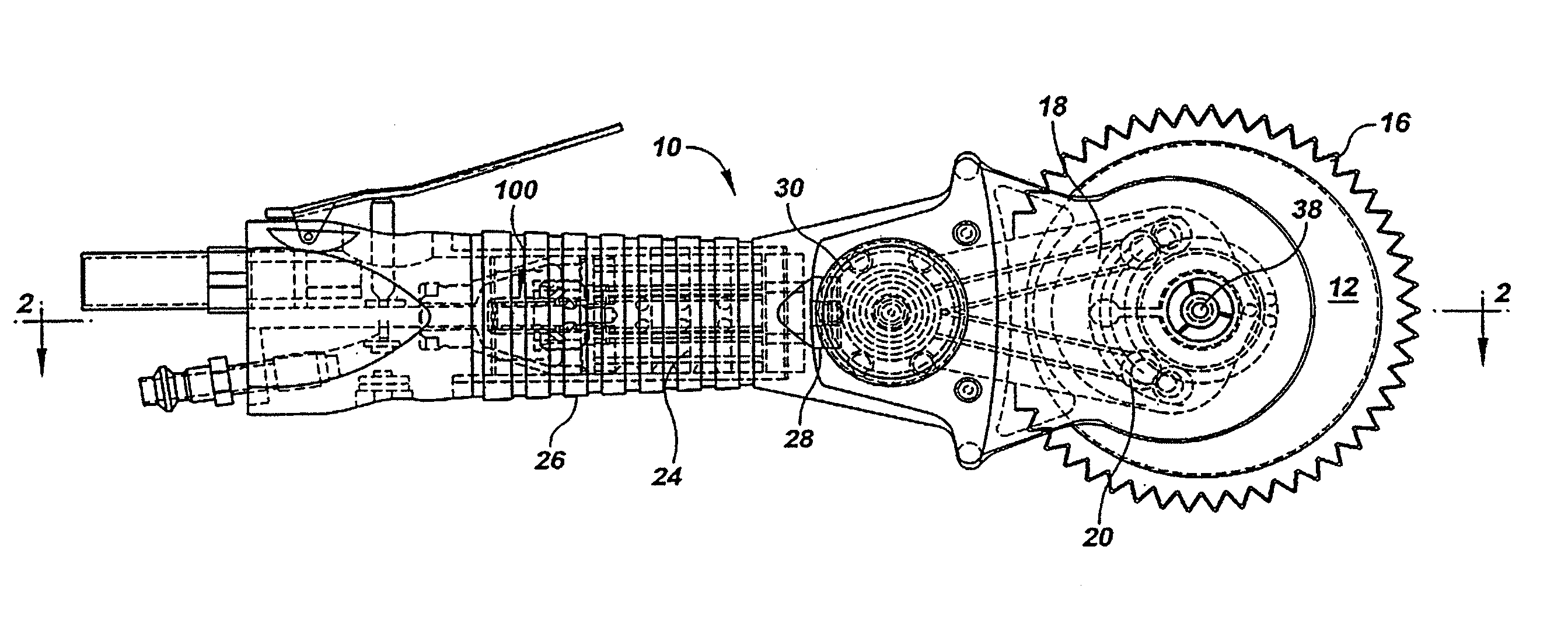
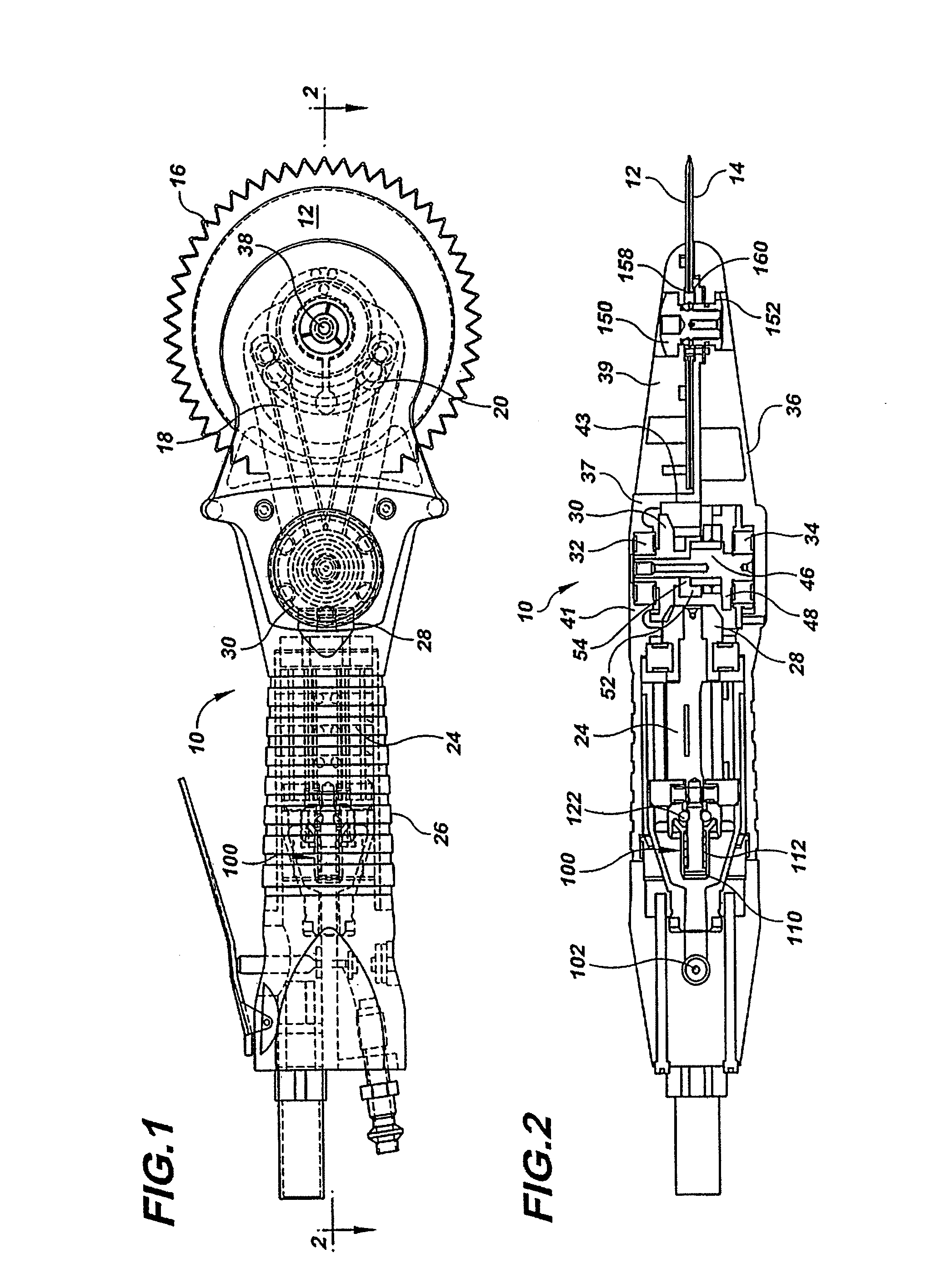
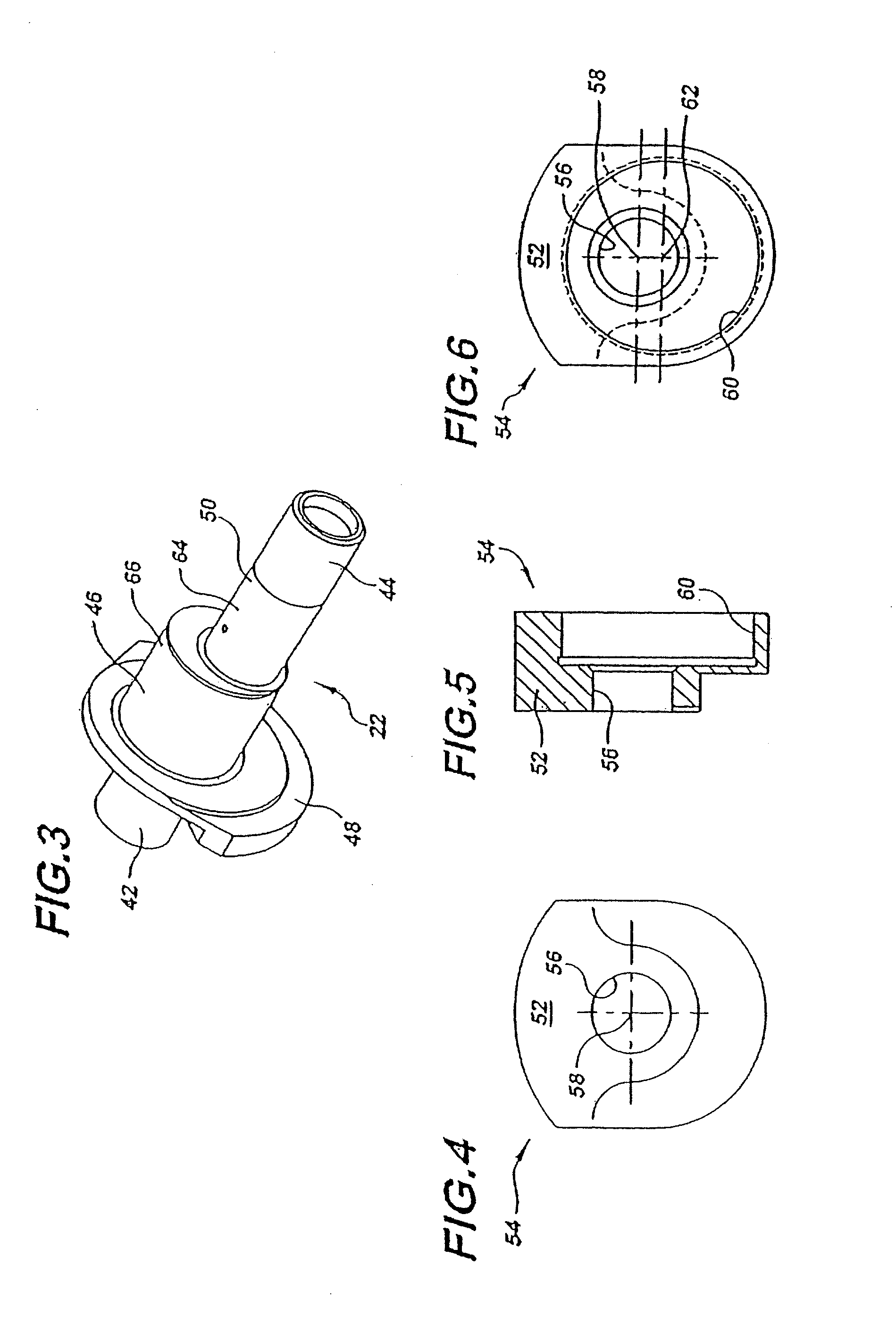
[0040]FIGS. 1 and 2 show a handheld dehider 10 according to a first embodiment of the present invention. The dehider 10 includes a pair of adjacent cutting disks 12 and 14 having teeth 16 located around the perimeter of each disk. The cutting disks 12, 14 are driven by a pair of pushrods 18, 20 in opposed cutting oscillations by an eccentric shaft 22 (seen best in FIG. 3).

[0041]The eccentric shaft 22 is driven by pneumatic motor 24 located in the handle 26 of the tool housing. The motor 24 drives pinion gear 28, which engages and turns the main drive gear 30. The main drive gear 30 is mounted on the eccentric shaft 22 such that rotation of the motor and pinion gear turns the main drive gear and eccentric shaft to drive the pushrods and cutting disks.

[0042]The eccentric shaft 22 is held betwe...


PUM


Abstract

A dehider includes a pneumatic motor driving a pair of disk blades in opposed cutting oscillations and a governor that controls the speed of the motor. Governor balls, acting as centrifugal weights, spin with the motor and push against an inclined flange on a valve head to move the valve head towards a valve seat. The motion of the valve head compresses a biasing spring and restricts the flow of pressurized air as the desired speed is exceeded. As speed decreases, centrifugal force decreases and the biasing spring opens the valve to provide additional power to the motor. The disk blades are provided with a cylindrical central lip that substantially increases the area of the central bearing that the blades turn on and produces significantly longer blade life.

Description

BACKGROUND OF THE INVENTION[0001]1. Field of the Invention[0002]The present invention relates to handheld dehiders and powered skinning knives used to remove the hide of a carcass in a meat processing facility. More specifically, the present invention relates to dehiders that use a pair of cutting disks driven in opposed cutting oscillations.[0003]2. Description of Related Art[0004]Handheld dehiders are used in meat processing facilities to remove the hide from an animal carcass. The most common type of dehider includes a pair of adjacent cutting disks or blades that are driven in opposed cutting oscillations by a corresponding pair of pushrods. The basic design is shown in U.S. Pat. No. 5,122,092 assigned to Jarvis Products Corporation, the assignee of the present invention. Similar dehider designs are shown and described in U.S. Pat. Nos. 4,368,560, 3,435,522 and 2,751,680.[0005]In the dehider design described in the patents above, each cutting blade includes teeth around its peri...

Claims


Application Information

Patent Timeline
Patent Type & Authority Patents(United States)
IPC IPC(8): A22B5/16
CPCA22B5/163
Inventor GWYTHER, PETER
Owner JARVIS PROD
Why Eureka
Try Eureka