
Mechanic's creeper

a creeper and mechanic technology, applied in the field of creepers, can solve the problems of common creeper design that does not provide a safe work environment and is generally vulnerable to severe injury to mechanics

Inactive Publication Date: 2010-06-01
SIEB KRISTOPHER +1
View PDF3 Cites 24 Cited by
  • Summary
  • Abstract
  • Description
  • Claims
  • Application Information

AI Technical Summary

Benefits of technology

[0005]In order to address the above and other drawbacks of known creepers, it is an aim of the present invention to provide a creeper adapted to provide protection to a user thereof from a falling object.
[0007]Still in accordance with the present invention, there is provided a creeper for protecting a user in a supine position when manoeuvring under a raised object, the creeper comprising a user support surface and a safety structure, the safety structure comprising at least one upwardly projecting head protective element disposed towards a first longitudinal end of the surface and at least one upwardly projecting body protective element disposed towards a second longitudinal end of the surface, the protective elements defining a protective space above at least a portion of the surface. The at least one head protective element and the at least one body protective element are longitudinally spaced apart and define a longitudinal space therebetween, thereby providing the user substantially unobstructed access to the object from the surface within the longitudinal space.
[0008]Still further in accordance with the present invention, there is provided a creeper for protecting a user in a supine position when manoeuvring under a raised object, the creeper comprising a user support surface, displacement means, load-absorbing means and a safety structure, the safety structure comprising at least one upwardly projecting rigid element defining a protective space above at least a portion of the surface. The displacement means are structurally coupled to the safety structure via the load-absorbing means such that, when the safety structure is subjected to the weight of the object, the load-absorbing means retracts the displacement means relative to the surface.

Problems solved by technology

However, it has been found that the common creeper design does not provide for a safe work environment.
Since common creepers do not provide any type of body or head protection for the mechanic working underneath the raised vehicle, the mechanic is generally vulnerable to severe injury in the event the vehicle should fall from its raised position.

Method used


Image

  • Mechanic's creeper
  • Mechanic's creeper
  • Mechanic's creeper

Examples


Embodiment Construction

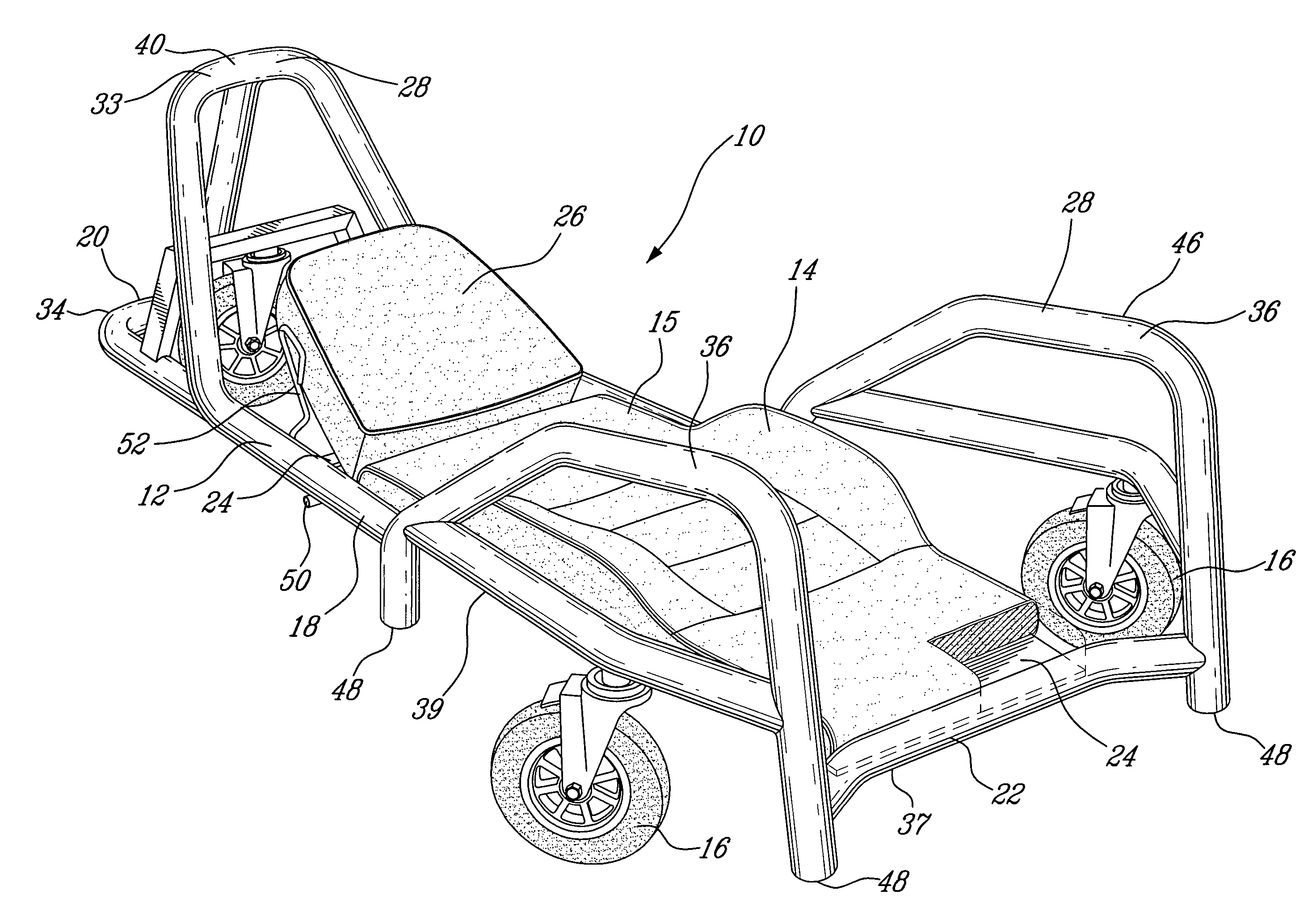
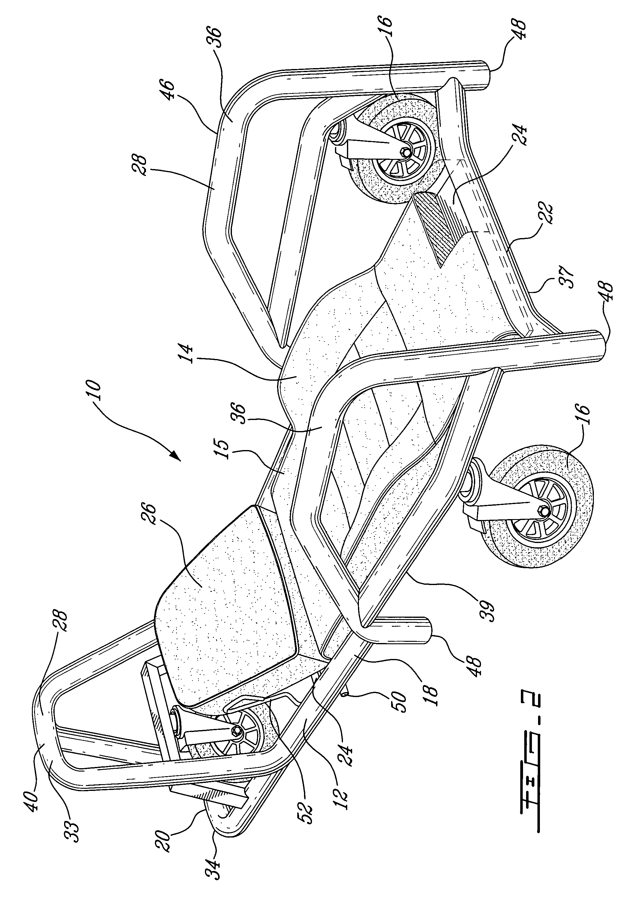
[0022]Referring now to FIG. 2, a mechanic's creeper, generally referred to using the numeral 10, and in accordance with an illustrative embodiment of the present invention, will now be described. The creeper 10 is generally for use by a professional or novice mechanic, or any individual for that matter that seeks to obtain access, generally in a supine position, to the under body of a vehicle or other such heavy machinery (not shown) for maintenance, inspection, general reparation or any other such activity. The vehicle in question may be raised using a standard jack or jack stands, or any other such device that will allow the vehicle to be raised sufficiently to allow the individual to work in a supine position underneath it.

[0023]The creeper 10 generally comprises a frame or framework 12, a user support surface 14 coupled thereto and a set of casters, wheels or other such displacement means 16 rotatably and typically pivotally mounted thereunder. The framework 12 generally defines...


PUM


Abstract

A creeper is disclosed for protecting a user in a supine position when manoeuvring under a raised object. The creeper comprises a user support surface and a safety structure. The safety structure comprises at least one upwardly projecting rigid element defining a protective space above at least a portion of the support surface. A foldable creeper which folds into a work bench and comprises a similar safety structure is also disclosed.

Description

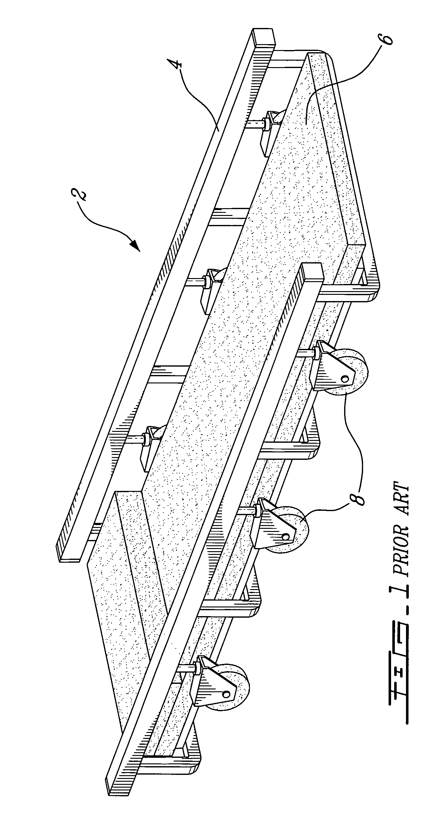
CROSS REFERENCE TO RELATED APPLICATIONS[0001]This application claims priority on U.S. provisional application No. 60 / 647,025, filed on Jan. 27, 2005, herein incorporated by reference.FIELD OF THE INVENTION[0002]The present invention relates to creepers and, more specifically, to creepers for use in manoeuvring under an object such as a motor vehicle.BACKGROUND OF THE INVENTION[0003]Creepers for use in working or manoeuvring beneath automobiles, trucks and other such motor vehicles are well known and have been used by the novice and professional automobile mechanic for years. Such known creepers, as exemplarily illustrated by the creeper 2 in FIG. 1, are generally comprised of a framework 4 to which is mounted a substantially flat body support surface 6 upon which a user may rest his head and / or back, and a set of wheels or casters 8 allowing the creeper to be displaced below a vehicle (not shown).[0004]However, it has been found that the common creeper design does not provide for a ...

Claims


Application Information

Patent Timeline
Patent Type & Authority Patents(United States)
IPC IPC(8): B25H5/00
CPCB25H5/00
Inventor SIEB, KRISTOPHERSIEB, ERIK
Owner SIEB KRISTOPHER
Learn More