
Method and apparatus for fair flow control and congestion avoidance supporting multiple QoS class requirements

a flow control and congestion avoidance technology, applied in electrical equipment, digital transmission, data switching networks, etc., can solve the problems of scarifying the scalability of the solution, not being able to achieve fair bandwidth allocation between all flows, and not being able to achieve the effect of achieving scalability and avoiding congestion

Inactive Publication Date: 2010-06-01
ROSBERG ZVI
View PDF13 Cites 13 Cited by
  • Summary
  • Abstract
  • Description
  • Claims
  • Application Information

AI Technical Summary

Problems solved by technology

Although prior art provide a plurality of flow control methods, none of which handle multiple QoS classes in a manner that guarantee end-to-end QoS requirements for all flows, neither can they achieve fair bandwidth allocation between all flows and all QoS classes.
Another prior art method, the Integrated Services QoS architecture, aka IntServ, does guarantee end-to-end performance behavior but scarifies the scalability of the solution, hence applicable only for small networks.
Therefore, prior art TCP flow control suits only best-effort traffic flows.
Prior art flow controls for streaming applications are rate-based and utilize the local network configuration of the user device to determine each rate target; these rates are not necessarily achievable.
This prior art specifications are not addressing fair flow control for multiple flow QoS classes.

Method used


Image

  • Method and apparatus for fair flow control and congestion avoidance supporting multiple QoS class requirements
  • Method and apparatus for fair flow control and congestion avoidance supporting multiple QoS class requirements
  • Method and apparatus for fair flow control and congestion avoidance supporting multiple QoS class requirements

Examples


Embodiment Construction

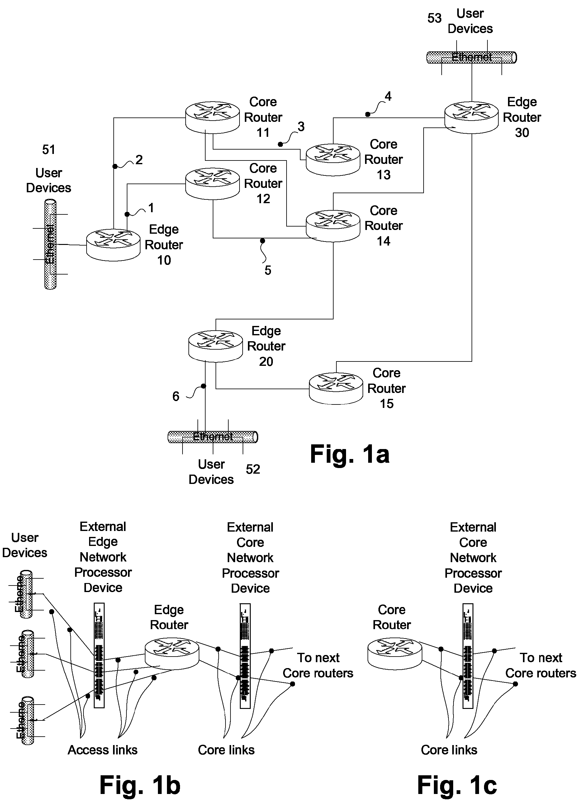
[0033]A simplified block diagram of an exemplary communication network is shown in FIG. 1a. The network comprises a plurality of edge routers, e.g., 10, 20, 30, and core routers, e.g., 11, 12, 13, 14, 15, interconnected by a plurality of links. For example, link 1 connects edge router 10 and core router 12; and link 3 connects core router 11 and core router 13. Each link may represent either a single hop physical link or a logical link comprising multiple hops defined in an underlying transport network such as FR, ATM, MPLS and GMPLS. Such logical links appear to the IP network layer as a single hop link. Furthermore, different subsets of routers and links may belong to different administrative domains, e.g., ISPs, Telecom companies. Hereinafter, such general communication network comprising core routers, edge routers and connecting links is referred to in the present invention as a backbone network. User devices, e.g., 51, 52, 53, which are the end sources and end destinations of t...


PUM


Abstract

For communication networks comprising user devices, edge routers, core routers, access and core links, a specification is given for a novel method and apparatus computing and allocating fair transmission rates to user data flows from a plurality of quality of service levels. The fair rates satisfy the minimum transmission rates, the end-to-end delays and the data loss rates required by each flow and also avoid network congestion. The method comprises: an edge router process and a flow control shaper for each edge router and a core router process for each edge and core router. All processes are executed in a distributed and asynchronous manner, are stable and converge to the desired fair rates. Each flow shaper process shapes the transmission rates based on local measurements driving them to the desired fair rates. The processes are efficient and lend themselves into ASIC and network processor unit implementations.

Description

CROSS-REFERENCE TO RELATED APPLICATION(S)[0001]The present application claims the benefit of U.S. Provisional Application No. 60 / 809,333 filed May 31, 2006, which is herein incorporated by reference.BACKGROUND OF THE INVENTION[0002]1. Field of Invention[0003]The present invention relates to a method and apparatus for adaptive allocation of fair bandwidth in the links attached to routers of a backbone network comprising edge routers, core routers and links serving a plurality of flows from a plurality of Quality of Service (QoS) classes, so as to meet the end-to-end QoS requirements of each flow, avoid network congestion and utilize the network resources optimally.[0004]2. Description of Prior Art[0005]A backbone (communication) network comprises a plurality of edge and core routers interconnected by a plurality of links facilitating data communication between end user applications running in user computer devices at the user premises. The user devices, which comprise the end sources...

Claims


Application Information

Patent Timeline
Patent Type & Authority Patents(United States)
IPC IPC(8): H04L12/28
CPCH04L47/10H04L47/22H04L47/2408H04L47/2416H04L47/33H04L47/263H04L47/27H04L47/283H04L47/2441
Inventor ROSBERG, ZVI
Owner ROSBERG ZVI
Learn More