
Method of and system for physically distributed, logically shared, and data slice-synchronized shared memory switching

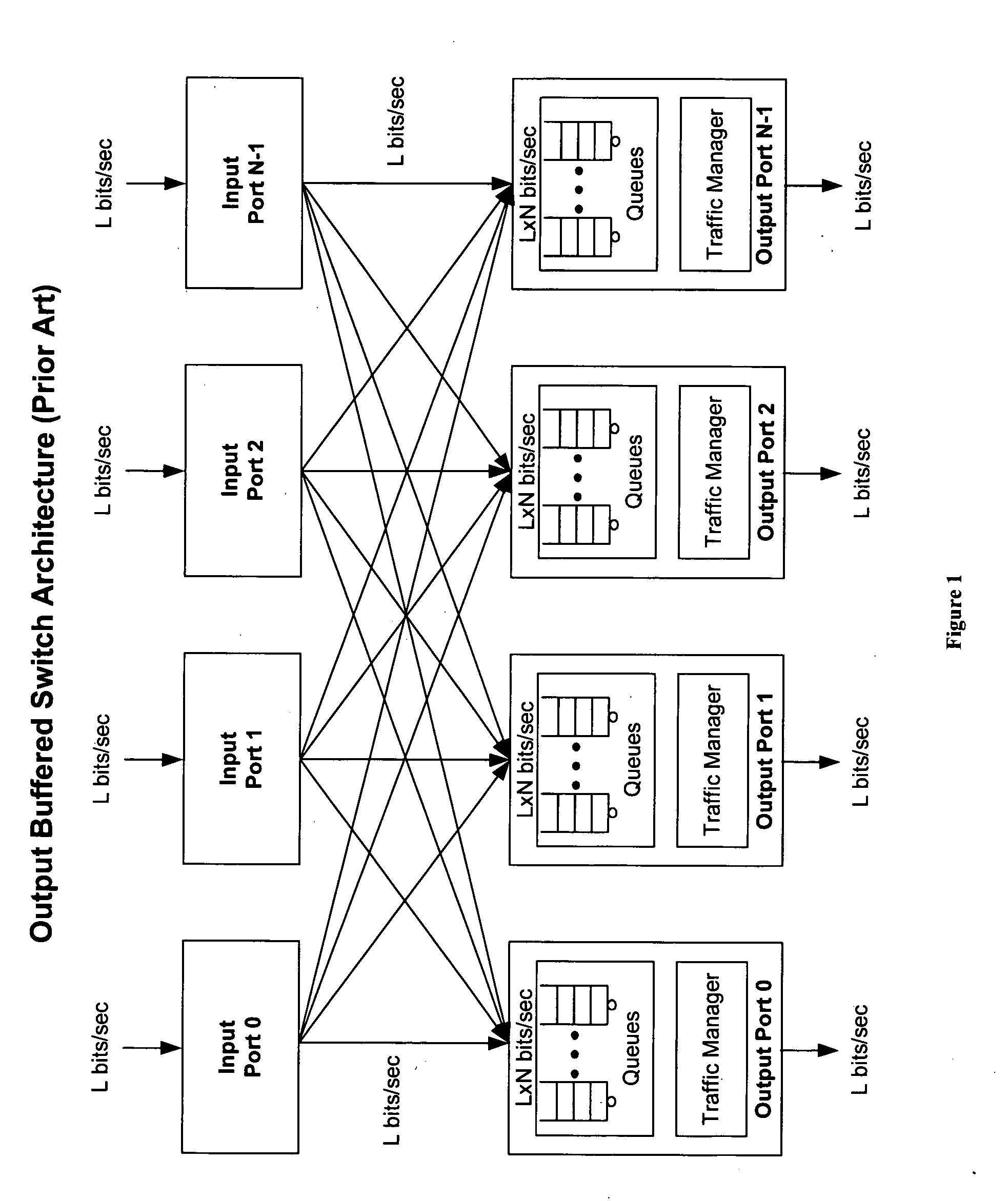
a shared memory and data slice technology, applied in data switching networks, data division multiplexes, instruments, etc., can solve problems such as fundamental head-of-line blocking problems in crossbar-based architectures, ineffective systems, and inability to implement ideal output buffer switches from interconnection and memory bandwidth perspectives, and achieve the effect of providing quality of servi

Inactive Publication Date: 2007-05-31
QOS LOGIX
View PDF4 Cites 298 Cited by
  • Summary
  • Abstract
  • Description
  • Claims
  • Application Information

AI Technical Summary

Benefits of technology

"The invention is a new and improved method of data switching that overcomes the limitations of previous techniques. It provides a non-blocking switch with a non-deterministic switching architecture that allows for ideal output-buffered data switching with traffic independence, low latency, and ideal egress bandwidth management and quality of service. The system is also more efficient, scalable, and cost-effective. The invention uses a novel data write path that does not require a separate control plane or centralized scheduler, and a distributed data control path architecture that allows for monitoring and controlling data queues in real-time. Overall, the invention provides a better and more efficient solution for shared-memory data switching."

Problems solved by technology

Fundamentally, data rates and port densities have grown drastically resulting in inefficient systems due to congestion between ingress or input and egress or output (I / O) ports.
For large values of N and L, however, an ideal output-buffered switch is not practically implementable from an interconnections and memory bandwidth perspective.
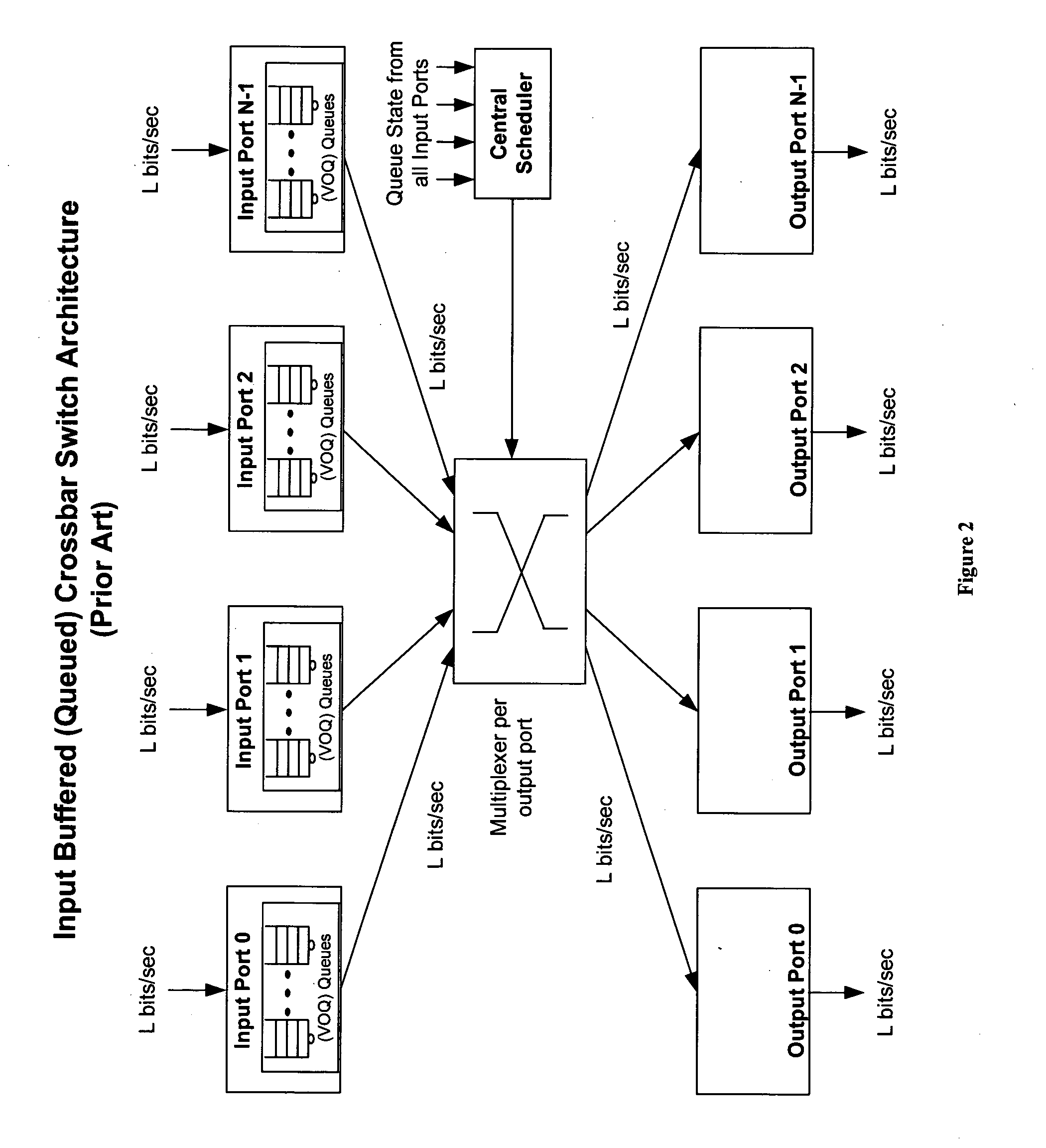
If multiple ingress ports request access to the same egress port simultaneously, however, the switch fabric must decide which ingress port will be granted access to the respective egress port and therefore must deny access to the other ingress ports.
Thus, crossbar-based architectures have a fundamental head-of-line blocking problem, which requires buffering of data packets into virtual output queues (VOQs) on the ingress port card during over-subscription.
Even though priority is a consideration, these schedulers are not, in practice, capable of controlling bandwidth on a per queue basis through the switch, a function necessary to provide the desired per queue bandwidth onto the output line.
This, of course, is far more complex than simply providing throughput, and low latency and jitter cannot be guaranteed if the per queue bit-rate cannot be guaranteed.
The integration of bandwidth management features into a central scheduler, indeed, has overwhelming implementation problems that are understood by those skilled in the art.
For traffic scenarios where the over-subscription is greater then 4×, however, packets build up in the VOQs on the ingress ports, thus resulting in the before-mentioned problems of the conventional crossbar.
As a result, QOS cannot be guaranteed for many traffic scenarios.
Another important weakness is that an egress port may not be oversubscribed but instead may experience an instantaneous burst of traffic behavior that exceeds the 4× overspeed.
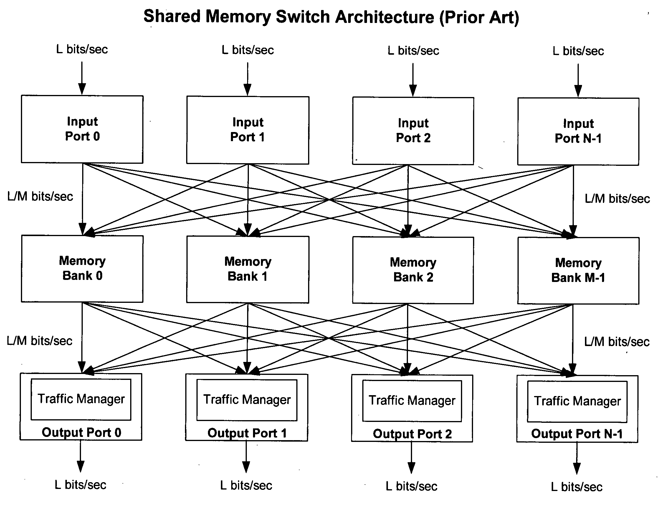
Practically, shared memory switch architectures to date, however, have other significant problems that have prevented offering the ideal QOS and scalability that is required by next generation applications.
Prior art approaches to deal with the challenges in the control architecture in actual practice have heretofore centered upon the use of a centralized control path, with the complexities and limitations thereof, including the complex control path infrastructure and overhead that are required to manage a typical shared-memory architecture.
In the case of small minimum size packets equal to a cell size, however, wherein subsequent packets are all going to different queues and the current state of the central scheduler is such that all the write pointers happen to be pointing to the same memory bank, every cell will be sent to the same bank, developing a worst-case burst.
This scheme therefore does not guarantee a non-blocking write path for all traffic scenarios.
While a FIFO per memory bank may absorb the burst of cells such that no data is lost, this is, however, at the expense of latency variation into the shared memory.
Even this technique, moreover, while working fine for today's or current routers with requirements of the order of a thousand plus queues, introduces scalability and latency problems for scaling the number of queues by, for example, a factor of ten.
In such a case, FIFOs sitting in front of the memory bank would have to be 10,000 times the cell size, resulting in excessively large latency variations, as well as scalability issues and expense in implementing the required memories.
Furthermore, while this approach simplified the control path in some ways, it still requires a centrally located compute intensive scheduler with communication paths between ingress and egress ports.
Although this is more efficient than a full mesh topology, system cost, implementation and scalability are impacted by the requirement for more links, board real estate and chip real estate for the scheduler.
The before-mentioned datapath problem, however, is directly related to the placement of cells across the banks due to a fixed scheduler scheme (FIG. 7) and thus the organization within a bank is not relevant because both schemes experience the same problem.
Such fragmented cell placement within a queue seriously compromises the ability of the system to deliver QOS features as in FIG. 7.
This obviously seriously compromises QOS.
Another problem that can arise in the above-mentioned prior art schemes is that cells within a queue can be read from the shared memory out of order.
This will require expensive reordering logic on the output port and also limits scalability.
Such techniques all have their complexities and limitations, including particularly the complex control path infrastructure and the overhead required to manage typical shared-memory architectures.
The cells are written across the M memory banks I+1 up to j cells, while the central scheduler increments the write pointer by j. As described before, this load-balancing scheme, however, can deleteriously introduce contention for a bounded time period under certain scenarios, such as where the central scheduler write pointers for all queues that happen to synchronize on the same memory bank, thus writing a burst of cells to the same memory bank.
A complex scheduling algorithm is indeed required to process N requests simultaneously, regardless of the incoming data rate and destination.
In summary, control messaging and processing places a tremendous burden on prior art systems that necessitates the use of a control plane to message addresses or pointers in a non-blocking manner, and requires the use of complex logic to sort addresses or pointers on a per queue basis for the purpose of enqueuing, gathering knowledge of queue depths, and feeding this all to the bandwidth manager so that it can correctly dequeue and read from the memory to provide QOS.
On the issue of preventing over-subscribing a memory bank, moreover, the invention provides a data write path that, unlike prior art systems, does not require the data input ports to write to a predetermined memory bank based on a load-balancing or fixed scheduling scheme, which may result in a fragmented placement of data across the shared memory and thus adversely affect the ability of the output ports to read up to the full output line-rate.

Method used


Image

  • Method of and system for physically distributed, logically shared, and data slice-synchronized shared memory switching
  • Method of and system for physically distributed, logically shared, and data slice-synchronized shared memory switching
  • Method of and system for physically distributed, logically shared, and data slice-synchronized shared memory switching

Examples


Embodiment Construction

[0124] Turning first to FIG. 10, the topology of the basic building blocks of the invention—ingress or input ports, egress or output ports, memory bank units, and their interconnections—is shown in the same format as the descriptions of the prior art systems of FIG. 1 through FIG. 9, with novel added logic units presented in more detail in FIG. 11 of the drawings.

[0125] At the ingress, a plurality N of similar ingress or input ports, each comprising respective line cards schematically designed as LC of well known physical implementation, is shown at input ports 0 through N−1, each respectively receiving L bits of data per second of input data streams to be fed to corresponding memory units labeled Memory Banks 0 through M−1, with connections of each input port line card LC not only to its own corresponding memory bank, but also to the memory banks of every one of the other input port line cards in a mesh M′ of N×M connections, providing each input port line card LC with data write ...


PUM


Abstract

An improved data networking technique and apparatus using a novel physically distributed but logically shared and data-sliced synchronized shared memory switching datapath architecture integrated with a novel distributed data control path architecture to provide ideal output-buffered switching of data in networking systems, such as routers and switches, to support the increasing port densities and line rates with maximized network utilization and with per flow bit-rate latency and jitter guarantees, all while maintaining optimal throughput and quality of services under all data traffic scenarios, and with features of scalability in terms of number of data queues, ports and line rates, particularly for requirements ranging from network edge routers to the core of the network, thereby to eliminate both the need for the complication of centralized control for gathering system-wide information and for processing the same for egress traffic management functions and the need for a centralized scheduler, and eliminating also the need for buffering other than in the actual shared memory itself,—all with complete non-blocking data switching between ingress and egress ports, under all circumstances and scenarios.

Description

FIELD OF INVENTION [0001] The present invention relates to the field of output-buffered data switching and more particularly to shared-memory architectures therefor, as for use in data networking and server markets, among others. [0002] The art has recognized that such architecture appears to be the best candidate for at least emulating the concept of an ideal output-buffered switch—one that would have infinite bandwidth through the switch, resulting in N ingress data ports operating at L bits / sec being enabled to send data to any combination of N egress data ports operating at L bits / sec, including the scenario of N ingress ports all sending data to a single egress port, and with traffic independence, no contention and no latency. [0003] In such an ideal or “theoretical” output-buffered switch, each egress port would be provided with a data packet buffer memory partitioned into queues that could write in data at a rate of N×L bits / sec, and read data at a rate of L bits / sec, thus al...

Claims


Application Information

Patent Timeline
Patent Type & Authority Applications(United States)
IPC IPC(8): H04L12/26H04L12/56
CPCH04L45/60H04L49/1515
Inventor PAL, SUBHASISRAY, RAJIBEPPLING, JOHN L.
Owner QOS LOGIX
Learn More