Submersible reverse osmosis desalination apparatus and method
What is AI technical title?
AI technical title is built by Patsnap AI team. It summarizes the technical point description of the patent document.
a reverse osmosis and salt water technology, applied in water cleaning, water treatment installations, electrical devices, etc., can solve the problems of increasing the number of people without water, and increasing the cost of water treatmen
Inactive Publication Date: 2010-06-08
TON THAT HUY
View PDF7 Cites 34 Cited by
Summary
Abstract
Description
Claims
Application Information
AI Technical Summary
This helps you quickly interpret patents by identifying the three key elements:
Problems solved by technology
Method used
Benefits of technology
Problems solved by technology
The increasing demand for water among households, industry, the environment, and especially agriculture is making global water scarcity a perilous possibility.
The world's thirst for water is likely to become one of the most pressing resource issues of the 21st Century.
Declining groundwater supplies, pollution, flooding and drought could well worsen poverty in many areas.
The depletion of aquifers is a new problem, one that has emerged only in the half past century or so, because it is only in this period that we have had the pumping capacity to quite literally deplete aquifers.
Energy costs for desalination of prior inventions is still high, and one of the main drawbacks to the use of reverse osmosis systems as used by the prior art is the pumping energy required for raising the sea water to the pressures necessary for osmotic separation.
The problem is amplified by the increasing cost of energy and the ongoing decreasing supply of available energy resources.
The above cited prior art inventions have attempted to save pumping energy by using the hydrostatic pressure of the ocean to desalinate seawater by reverse osmosis, but none of them have proved to be practical or economically viable since they all require the invention to be placed at great depths above 3,000 feet in order to obtain the required pressure of 800 to 1000 psi for osmotic separation.
The amount of energy saved by such a process is offset by installation and maintenance costs since it requires working in extremely deep waters.
Furthermore the important head requires substantial energy to pump the fresh water to the surface.
The expansion of present facilities is only limited by the offshore operating area granted by the local authorities.
In absence of sufficient currents or water mixing at the disposal spot, the accumulation of concentrated brine could be harmful for the sea flora and fauna.
Method used
Image
Click on the blue label to locate the original text in one second.
Reading with bidirectional positioning of images and text.
Examples
Embodiment Construction
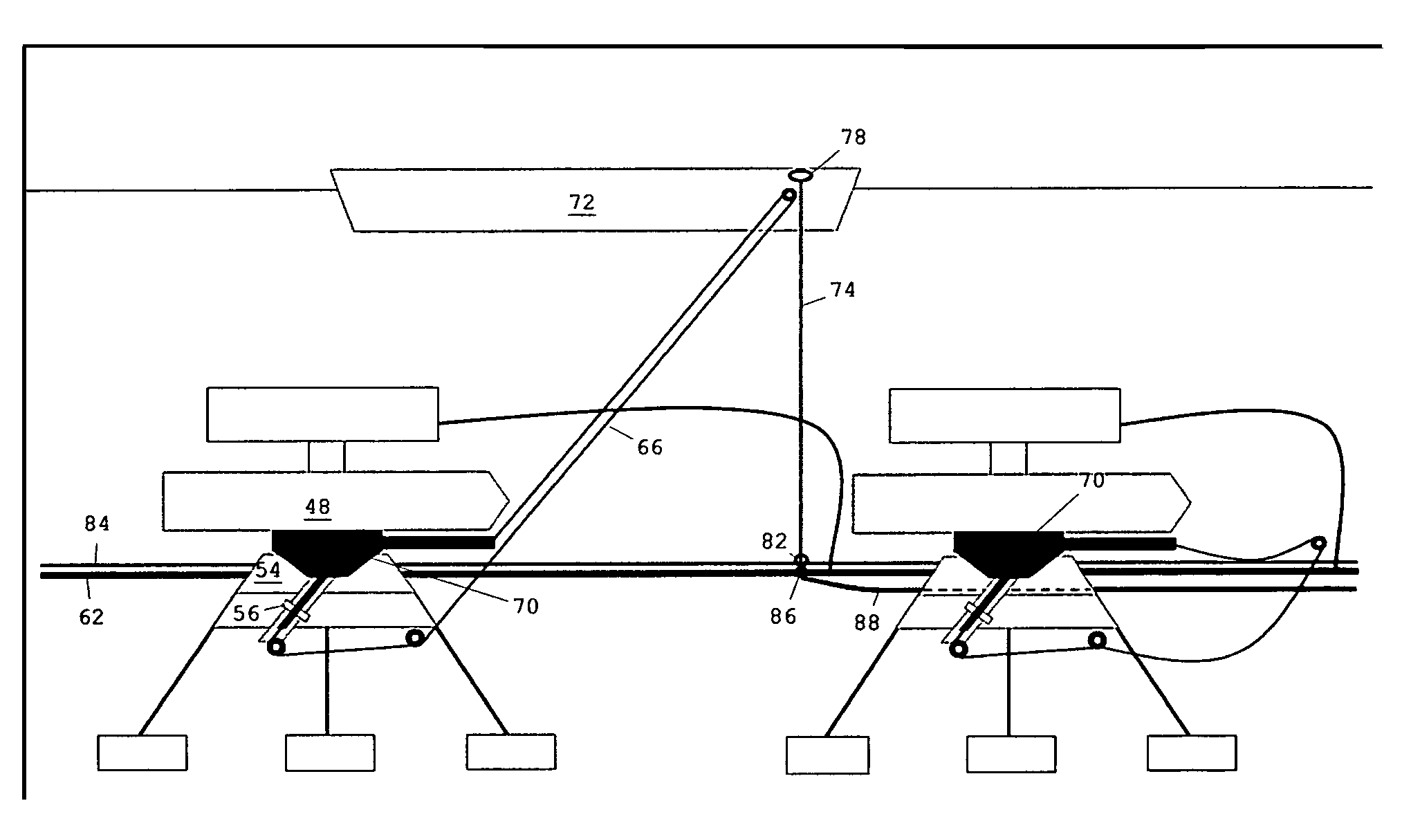
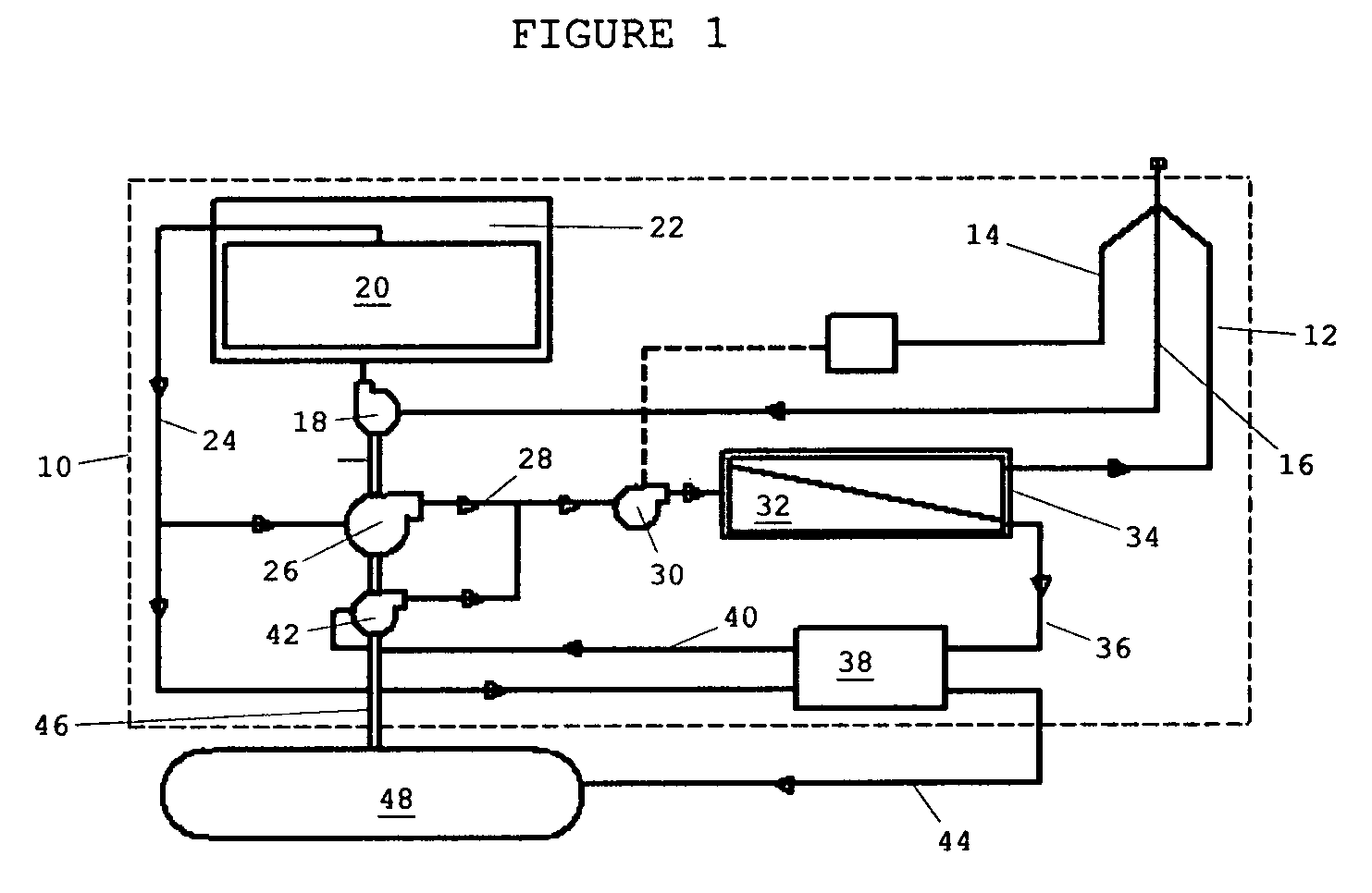
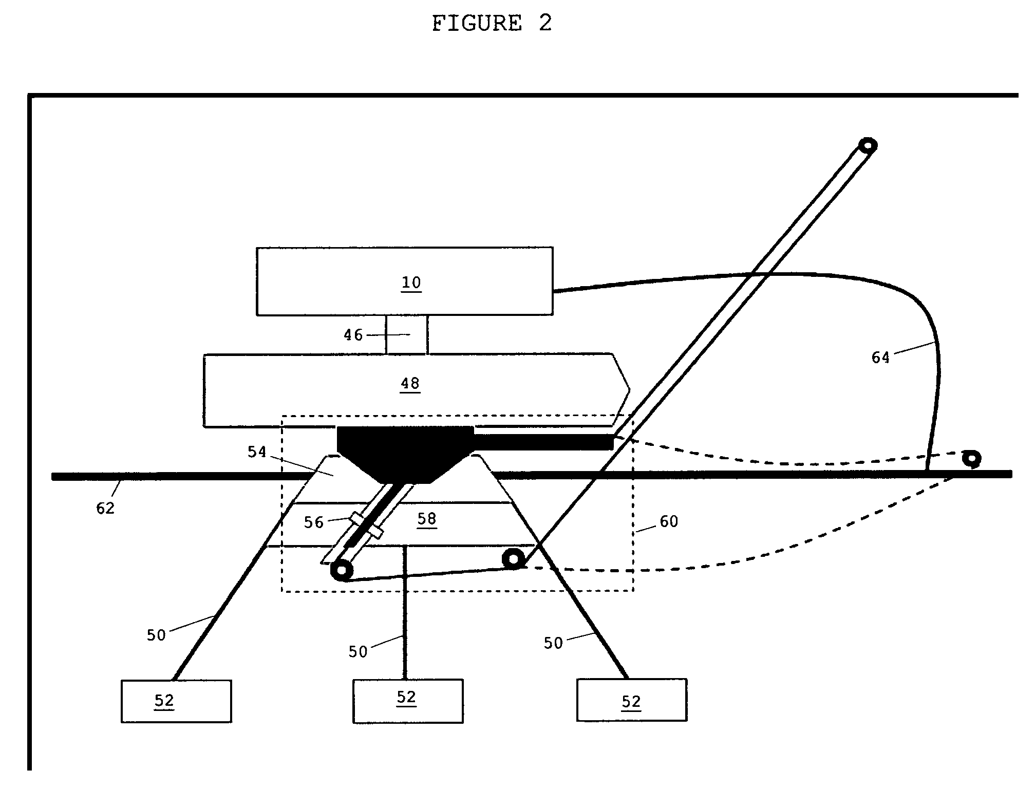
[0042]Referring now to FIG. 1: The apparatus is comprised of equipment necessary for the seawater reverse osmosis contained in a main body or frame 10 removably attached and made of materials not overly subject to the problems of salt or brackish water such as a fiber reinforced plastic intended to be immersed into the marine medium at a depth of less than 1200 ft. A main flexible pipeline 62 and a secondary flexible pipeline 64 which both include a permeate pipeline 12 made of a flexible material substantial enough to withstand sustained external pressures of greater than 34 PSI, a seawater resistant power line 14 such as a WPI Burton Engineering Underwater Power Cable and an air pipeline 16 made of a flexible material substantial enough to withstand sustained external pressures of greater than 34 PSI which therefore connects the apparatus to shore.
[0043]Pre-filtration is provided by a set of submerged hollow fiber membranes known as the pre-filtration hollow fiber membrane set 20 ...
PUM
Abstract
An submersible desalination unit composed of a structure containing a water intake system for acquiring sea water, a sea water pre-filtration system for removing lager contaminants and debris, a reverse osmosis system for the purification of the water, a permeate transfer system to carry the water to where it will be used, a power source for powering the equipment used in the process and a control system that operates and monitors the equipment and process of removing salt from the water and transferring the desalinated water to other use and returning the brine solution to the sea.
Description
RELATED APPLICATIONS[0001]The present application is related to U.S. Pat. No. 3,456,802, issued Jul. 22, 1969, included by reference herein.[0002]The present application is related to U.S. Pat. No. 4,125,463, issued Nov. 14, 1978, included by reference herein.[0003]The present application is related to U.S. Pat. No. 5,229,005, issued Jul. 20, 1993, included by reference herein.[0004]The present application is related to U.S. Pat. No. 6,800,201, issued Oct. 5, 2004, included by reference herein.FIELD OF THE INVENTION[0005]The present invention relates to an apparatus and method for desalination of salt water and, more particularly, to an apparatus and method for desalination of salt water by reverse osmosis.BACKGROUND OF THE INVENTION[0006]The increasing demand for water among households, industry, the environment, and especially agriculture is making global water scarcity a perilous possibility. However, salt or brackish water is readily available in many areas of the world. In fact...
Claims
Application Information
Patent Timeline
Application Date:The date an application was filed.
Publication Date:The date a patent or application was officially published.
First Publication Date:The earliest publication date of a patent with the same application number.
Issue Date:Publication date of the patent grant document.
PCT Entry Date:The Entry date of PCT National Phase.
Estimated Expiry Date:The statutory expiry date of a patent right according to the Patent Law, and it is the longest term of protection that the patent right can achieve without the termination of the patent right due to other reasons(Term extension factor has been taken into account ).
Invalid Date:Actual expiry date is based on effective date or publication date of legal transaction data of invalid patent.

