Rotary method for forming a vaginal applicator

a vaginal and applicator technology, applied in the field of forming a vaginal applicator, can solve the problems of malformation of the partially circumscribing raised portions, difficult manufacturing, and inability to form the applicator

Inactive Publication Date: 2010-06-15
THE PROCTER & GAMBLE COMPANY
View PDF23 Cites 2 Cited by
  • Summary
  • Abstract
  • Description
  • Claims
  • Application Information

AI Technical Summary

Problems solved by technology

Such an arrangement can be difficult to manufacture using a rotary process that employs a mandrel and die if there are both a raised portion that completely circumscribes the tampon applicator and raised portions that partially circumscribe the tampon applicator that are disposed close to one another along a common circumference.
The difficulty arises because to form the raised portion that completely circumscribes the tampon applicator, the die and forming mandrel must move relative to one another at least a distance equal to the outer circumference of the applicator tube.
Over forming the applicator in such a manner can result in malformation of partially circumscribing raised portions that are disposed close to one another along a common circumference.
Furthermore, if multiple equal length partially circumscribing raised portions disposed about a common circumference wherein the raised portions are separated from one another by a distance less than the magnitude of over forming desired to meet aesthetic constraints, over forming may not be a viable approach to form the applicator.
With these limitations in mind, there is a continuing unaddressed need for a method for forming a vaginal applicator that permits over forming a continuous raised portion about a circumference of the applicator yet still can produce an applicator having intermittent raised portions disposed close to one another along a common circumference.

Method used


Image

  • Rotary method for forming a vaginal applicator
  • Rotary method for forming a vaginal applicator
  • Rotary method for forming a vaginal applicator

Examples


Embodiment Construction

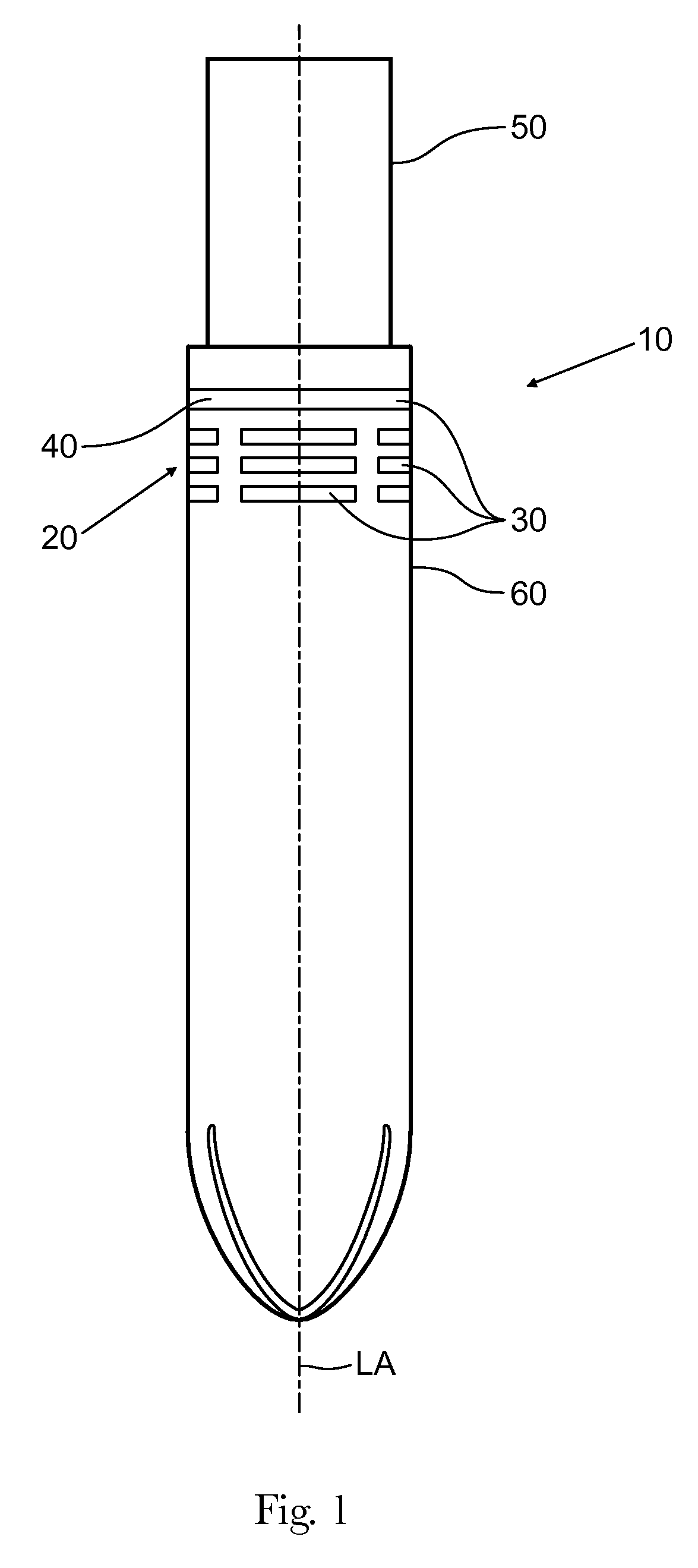
[0018]FIG. 1 is an illustration of a vaginal applicator 10 having applicator longitudinal axis LA, a gripping region 20, a plurality of raised portions 30, and a plunger 50. The applicator 10 can have at least one continuous raised portion 40, a continuous raised portion 40 being a subset of the class of raised portions 30. The applicator 10 may be formed from an applicator tube 60, the applicator tube 60 being a material including, but not limited to, cardboard, plastic, or other readably formable material. The vaginal applicator 10 can be a tampon applicator. The vaginal applicator 10 can be pessary applicator.

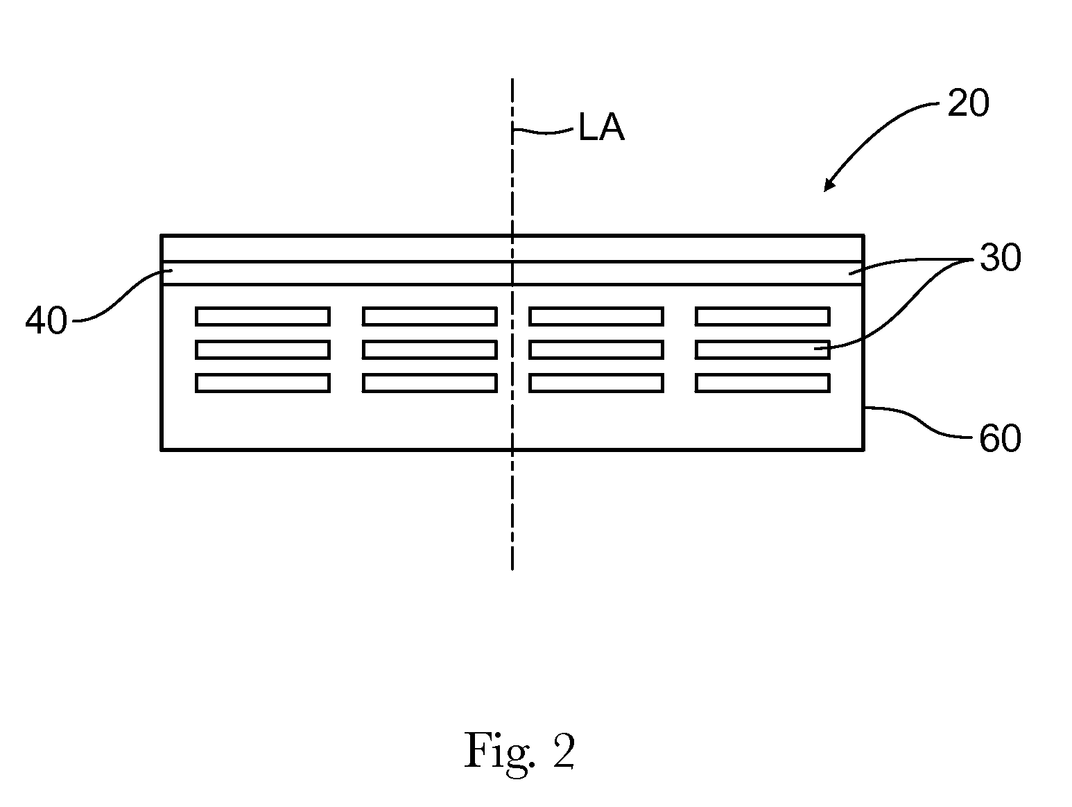
[0019]FIG. 2 is an illustration of an entire circumference of a gripping region 20. As illustrated in FIG. 2, in some embodiments, a plurality of raised portions 30 having equal length about the circumference of the applicator 10 and aligned along a common circumference at a particular location relative to the applicator longitudinal axis LA may be desirable.
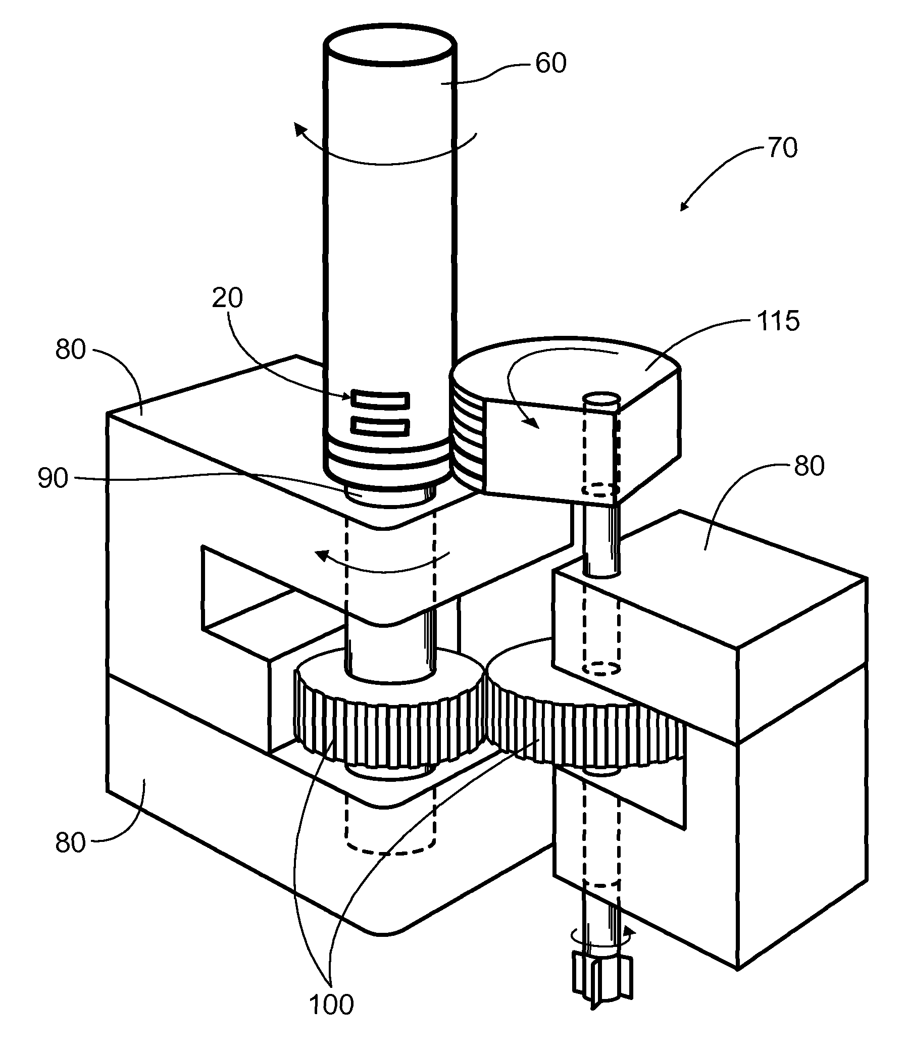
[0020]A forming ...


PUM

PropertyMeasurementUnit
thicknessaaaaaaaaaa
thicknessaaaaaaaaaa
thicknessaaaaaaaaaa

Abstract

A rotary method for forming a vaginal applicator. The method includes the steps of providing a forming mandrel, an applicator tube, and die then arranging the forming mandrel to be inside the applicator tube and then engaging the forming mandrel and the applicator tube with the die. The forming mandrel has a first sustaining ridge having a circumferential length and a second sustaining ridge having a circumferential length. The circumferential length of the first sustaining ridge is less than the circumferential length of the second sustaining ridge.

Description

FIELD OF THE INVENTION[0001]The invention relates to a method for forming a vaginal applicator.BACKGROUND OF THE INVENTION[0002]Feminine care products, such as tampons and pessaries, are generally used by women within the vagina for feminine needs, such as, e.g., to absorb menstrual or other body exudates, for pelvic support, and / or for other feminine needs. Such feminine products can be inserted into the vagina digitally, such as, e.g., by using a finger, or can be inserted into the vagina by using an applicator.[0003]Applicators typically can comprise an applicator tube and a plunger. The material to be expelled from the applicator tube, such as an absorbent tampon or pessary, can be positioned within the insertion member. The insertion member can have a first end for insertion of the material and a second end for receipt of the plunger. To use the applicator, the consumer will grasp the insertion member, position the first end appropriately, such as, e.g., into the body, and move...

Claims


Application Information

Patent Timeline
Patent Type & Authority Patents(United States)
IPC IPC(8): B31B1/28B31B50/28
CPCA61F13/26A61F13/2082
Inventor SONG, LIMINGILBERT, STEVEN RAYDAVIS, SCOTT ALBERT
Owner THE PROCTER & GAMBLE COMPANY
Why Eureka
Try Eureka