
Applicator

a technology of applicator and spherical body, which is applied in the field of applications, can solve the problems of inconvenient use, undesirable use, and the user of the applicator having to use both hands, and cannot be used in a vertical position all the time,

Active Publication Date: 2018-04-17
AM TUOTANTO
View PDF21 Cites 2 Cited by
  • Summary
  • Abstract
  • Description
  • Claims
  • Application Information

AI Technical Summary

Benefits of technology

[0016]An advantage of the applicator of the invention is that the applicator makes possible dispersing hair building solids onto the scalp one-headedly so that a hand position of the user is both ergonomic and natural because the applicator can be inclined according to the shape of the scalp without being clogged. Another advantage of the invention is that the applicator comprises an air pump which is electrically configured for creating an air flow so that the user only has to give an activation signal in order to create an air flow inside the applicator and to supply hair building solids. This removes the need for pumping a bulb or similar with a finger which tires out the finger.
is that the applicator comprises an air pump which is electrically configured for creating an air flow so that the user only has to give an activation signal in order to create an air flow inside the applicator and to supply hair building solids. This removes the need for pumping a bulb or similar with a finger which tires out the finger.

Problems solved by technology

One of the problems with the above mentioned applicator is that the applicator user has to use both hands to operate the applicator.
This is especially undesirable when spraying hair building solids because the user normally wants to use the free hand to reshape the hair.
One of the problems associated with the above applicator is that when using the applicator a normal working position follows the shape of the scalp which means that the applicator has to be in an inclined position and cannot be used in a vertical position all the time.
The inclined position causes clogging in the nozzle preventing hair building solids to come out from the nozzle and thereby makes the outcome unsatisfactory.

Method used


Image

  • Applicator
  • Applicator
  • Applicator

Examples


Embodiment Construction

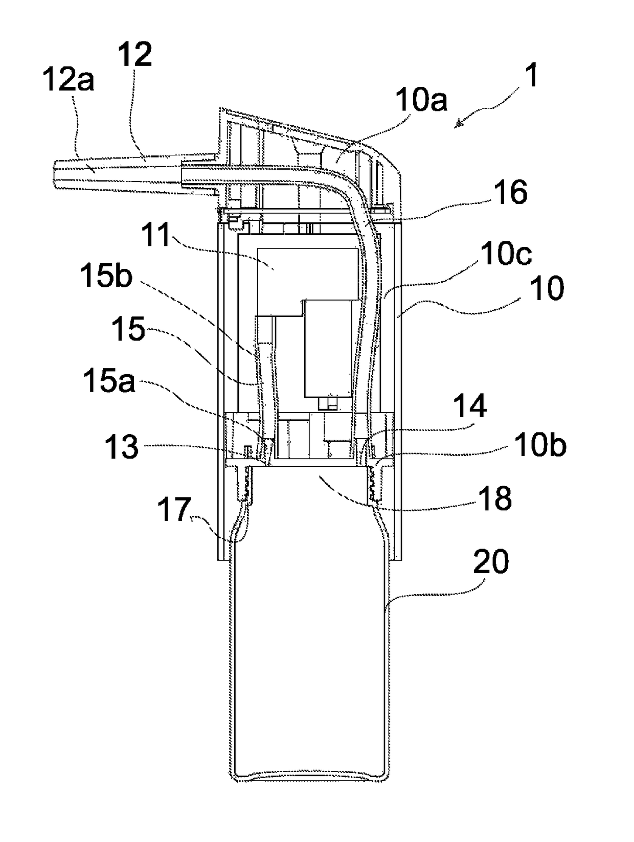
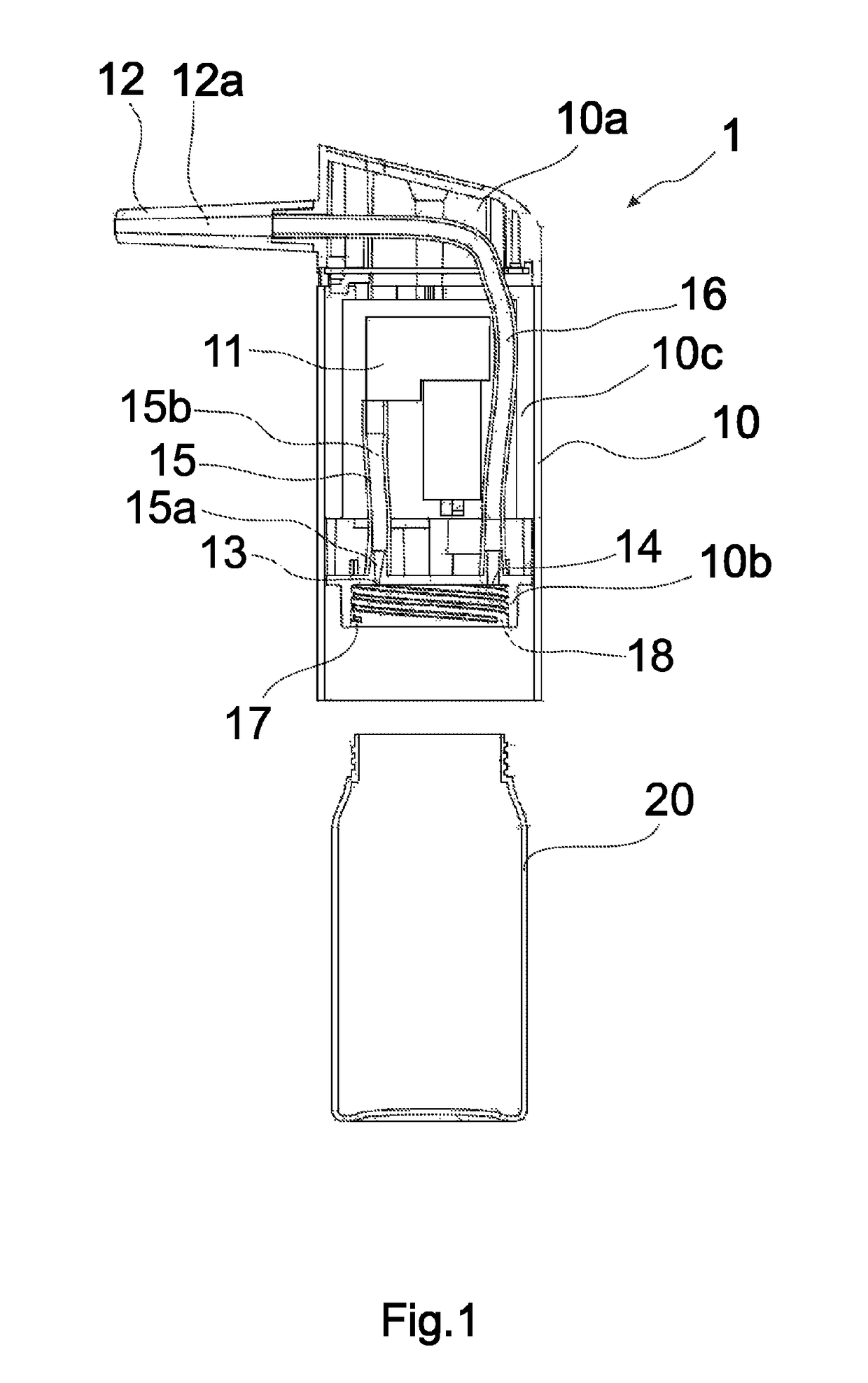
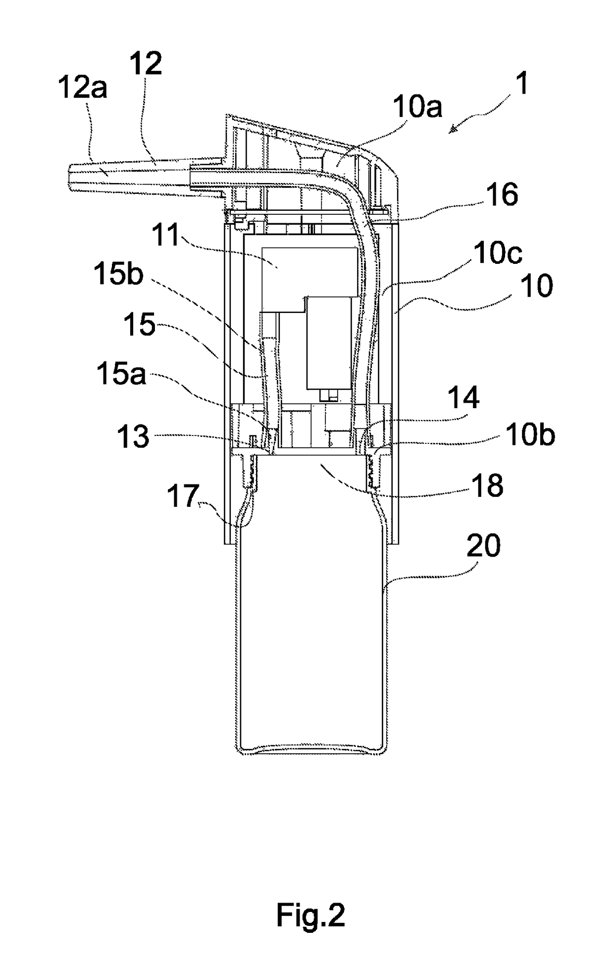
[0023]FIG. 1 shows the applicator 1 according to the invention which comprises an applicator body 10. The applicator body 10 is connectable with a container 20 comprising hair building solids (hair building solids are not shown in this figure). The applicator body 10 comprises a top part 10a, a bottom part 10b and a main part 10c extending between the top part 10a and the bottom part 10b. The top part 10a comprises a nozzle 12, the bottom part 10b comprises an attachment structure 17 for attaching the applicator body 10 to the container 20. The main part 10c of the applicator body 10 comprises an air pump 11 and a first channel 15 extending between the air pump 11 and a first orifice 13. The applicator body 10 further comprises a second channel 16 extending between a second orifice 14 and the nozzle 12. Part of the second channel 16 is arranged to extend in the top part 10a of the applicator body 10 such that it extends from the nozzle 12 in a first direction which is substantially ...


PUM


Abstract

An applicator for spraying hair building solids is configured for one-handed operation and includes an applicator body which is connectable with a container including hair building solids. The applicator body includes a top part, a bottom part and a main part extending between the top part and the bottom part; an air pump electrically configured for creating an air flow; and a nozzle for spraying hair building solids out from the applicator. The bottom part includes an attachment structure for attaching the container to the applicator body, a first orifice in flow connection with the air pump for delivering air flow from the air pump via the bottom part and a second orifice in flow connection with the nozzle for delivering hair building solids via the bottom part to the nozzle.

Description

CROSS-REFERENCE TO RELATED APPLICATION[0001]This application claims priority to European Patent Application No. 15156544.7, filed Feb. 25, 2015, which is incorporated by reference herein in its entirety.BACKGROUND[0002]Field[0003]The present invention relates to an area of cosmetic treatment for hair loss and especially to an applicator for spraying hair building solids, more particularly to an applicator which is configured for one-handed operation and is defined in the independent claim 1.[0004]Description of the Related Art[0005]Different applicators for hair building solids are known in the prior art which with the help of air suspend hair building solids from the applicator onto a human scalp for covering areas of the scalp which do not comprise hair.[0006]Publication WO 2005 / 009624 shows an applicator which is operated with both hands such that one hand holds the applicator and the other hand squeezes a rubber bulb in order to create an air flow through an air supply tube to a...

Claims


Application Information

Patent Timeline
Patent Type & Authority Patents(United States)
IPC IPC(8): B65D88/54B05B11/06A45D19/00A45D34/04A45D19/16B05B7/24B05B1/02
CPCB05B7/2416A45D19/0008A45D19/16A45D34/04B05B11/061B05B1/02B05B11/062A45D2019/0058A45D2200/057A45D19/012A45D19/005
Inventor MARTISKAINEN, ARTOKUITTO, JANNEKUITTO, JARMO
Owner AM TUOTANTO
Learn More