
Shower base with flow enhancing covered drain

a technology of shower enclosure and drain, which is applied in the field of drain at the base of the shower enclosure, can solve the problems of reducing the effective passage area, reducing the usable floor space in the enclosure, and reducing the flow rate, so as to increase the flow rate through the drain and enhance the flow characteristics

Active Publication Date: 2010-06-22
KOHLER CO
View PDF14 Cites 54 Cited by
  • Summary
  • Abstract
  • Description
  • Claims
  • Application Information

AI Technical Summary

Benefits of technology

[0017]Thus, the shower base receptor and drain assembly of the present invention provides a covered drain system with enhanced flow characteristics, particularly increased flow rate through the drain when compared to an uncovered drain of the same opening dimension.

Problems solved by technology

However, the openings in the grate must be left unblocked and otherwise make it uncomfortable to stand on with bare feet, and therefore, the usable floor space in the enclosure is effectively reduced by the area of the grate where a person in the shower would avoid standing.
However, this type of covered drain typically significantly reduces the effective passage area through which water can drain, thereby reducing flow rate and possible causing flow back-up and standing water in the base receptor.
Standing in drain water is unpleasant, and the raised water can slip over the short rim of the receptor base.
The slow drain problem is exacerbated when the water passing through the drain forms a vortex caused by the coriolis effect arising from suction through the drain.
The unoccupied space in the center of the drain thus effectively diminishes the passage area of the drain, and in further slows the flow rate.
The disclosed drain would be too large and cumbersome for use in a shower receptor.
Moreover, like other conventional covered drains, the reduction in drain passage area caused by use of the cover would slow the flow rate through the drain excessively in gravity feed drainage systems, such as shower applications, such that water would likely accumulate around the drain.

Method used


Image

  • Shower base with flow enhancing covered drain
  • Shower base with flow enhancing covered drain
  • Shower base with flow enhancing covered drain

Examples


Embodiment Construction

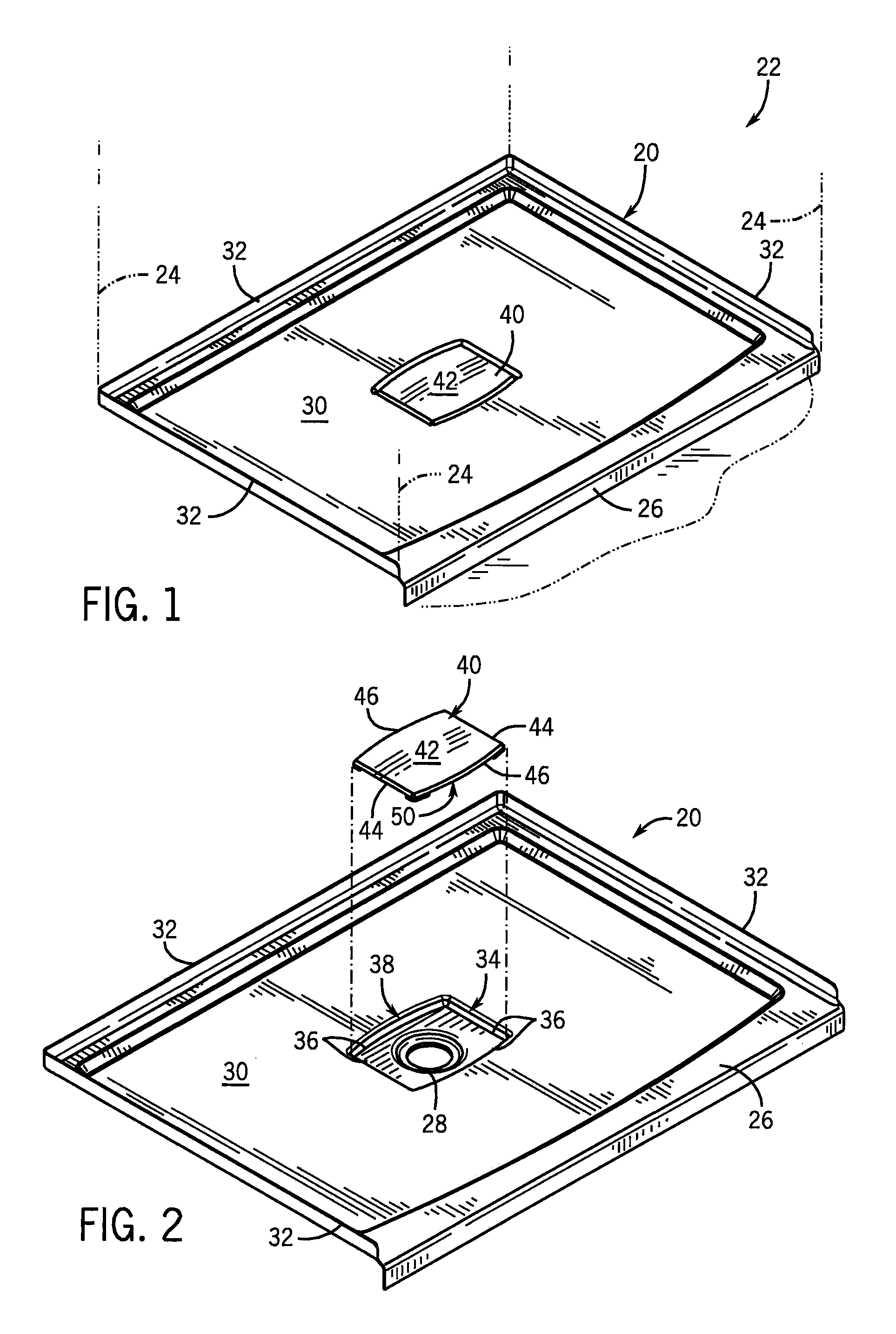
[0029]The accompanying FIGS. 1-10 illustrate a preferred embodiment of a base and drain assembly 20 according to the present invention for a shower enclosure, referred to generally by numeral 22. The term “shower enclosure” is used herein to refer to an area where water is sprayed down onto a person that is either standing or sitting. This area can have one or more upright walls 24, three walls are shown in phantom in FIG. 1, and a door or curtain (not shown) so that it is either fully or partially enclosed along one or more sides or the entire boundary of the area. Although not shown, a curtain or a pivotal door could be mounted at the front of the shower enclosure 22 for privacy and to keep water from splashing out of the enclosure.

[0030]The assembly 20 includes a receptor base 26 providing a drain opening 28 and floor 30 of the shower enclosure 22. The upright walls 24 are supported by the receptor base 24 along the peripheral edges and adjacent the rear and side flanges 32. The ...


PUM


Abstract

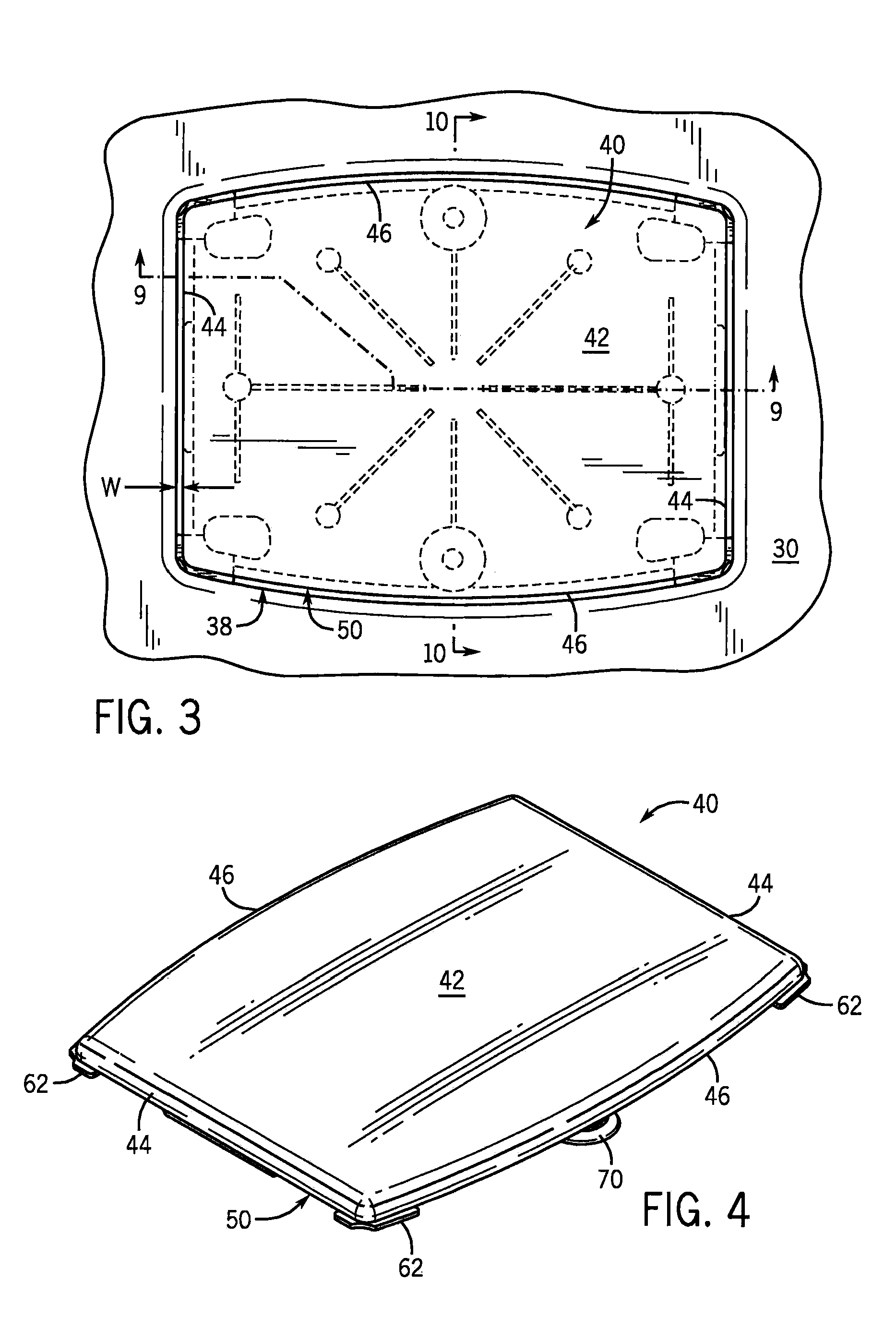
A shower enclosure base has a flow enhancing flush-mounted drain cover that conceals the drain opening and provides a flat stepping surface. Drain flow is achieved through a narrow peripheral passage between the drain cover and the drain well in which it is seated. Despite the reduced flow area of passage, flow enhancing features of the drain cover serve to improve the flow rate through the drain. These features are radially converging ribs at the underside of the drain cover that interrupt the natural tendency for drain water to form a vortex as it passes into and through a circular drain opening. The drain cover can be removably secured to the base by suction cups that attach to the drain well.

Description

CROSS-REFERENCE TO RELATED APPLICATION[0001]Not applicable.STATEMENT OF FEDERALLY SPONSORED RESEARCH OR DEVELOPMENT[0002]Not applicable.BACKGROUND OF THE INVENTION[0003]The present invention relates to plumbing fixtures, and more particularly to the drain at the base of a shower enclosure.[0004]Bathroom plumbing fixtures such as bath tubs, spas, whirlpools, shower stalls, shower surrounds, free standing partial or full shower enclosures, etc., are well known. Such fixtures can be installed in combination or as separate and discrete fixtures. In the case of stand alone shower enclosures, the upright walls that surround the enclosure are typically mounted onto to a generally flat base, sometimes referred to in the industry as a shower or base “receptor”. U.S. Pat. No. 3,457,568 provides an example of a prior art base receptor.[0005]In addition to supporting the enclosure walls, the shower base receptor is also the floor of the enclosure on which a person stands during a shower. As suc...

Claims


Application Information

Patent Timeline
Patent Type & Authority Patents(United States)
IPC IPC(8): A47K3/00
CPCA47K3/40E03F5/0408E03C1/22
Inventor WITT, KEVIN L
Owner KOHLER CO
Learn More