Aircraft engine assembly

a technology for aircraft engines and components, applied in the direction of power plant construction, aircraft power plants, transportation and packaging, etc., can solve the problems of high friction between the turning compressor and the turbine blade and the delivery casing, adversely affecting the lifetime of the engine, and its performance, so as to reduce the friction between the rotating compressor and the distancing one from the other, the effect of reducing flexing

Inactive Publication Date: 2010-06-22
AIRBUS OPERATIONS (SAS)
View PDF6 Cites 20 Cited by
  • Summary
  • Abstract
  • Description
  • Claims
  • Application Information

AI Technical Summary

Benefits of technology

[0017]Consequently, the above mentioned reduction in flexing leads to a significant reduction in the friction between the rotating compressor and turbine blades and the delivery casing of the engine, and thereby limits to a great extent the losses in efficiency due to wear of said blades.
[0034]Moreover, the plurality of cradles may also comprise two supporting cradles for the lateral cradles for taking up thrust stresses, said two supporting cradles being arranged respectively on either side of the centre box and each integral on the one hand with one of the two lateral cradles, and on the other hand with the centre box. Advantageously, the supporting cradles are arranged in such a way as to work in traction, and make it possible to avoid the bending of the lateral cradles for taking up thrust stresses.

Problems solved by technology

When this type of longitudinal flexing occurs, particularly during the cruising phases of the aircraft, high friction then arises between the turning compressor and turbine blades and the delivery casing of the engine.
The main consequence of the friction encountered resides in a premature wear of the engine, which naturally adversely affects the lifetime of said engine, as well as its performance.

Method used


Image

  • Aircraft engine assembly
  • Aircraft engine assembly
  • Aircraft engine assembly

Examples


Embodiment Construction

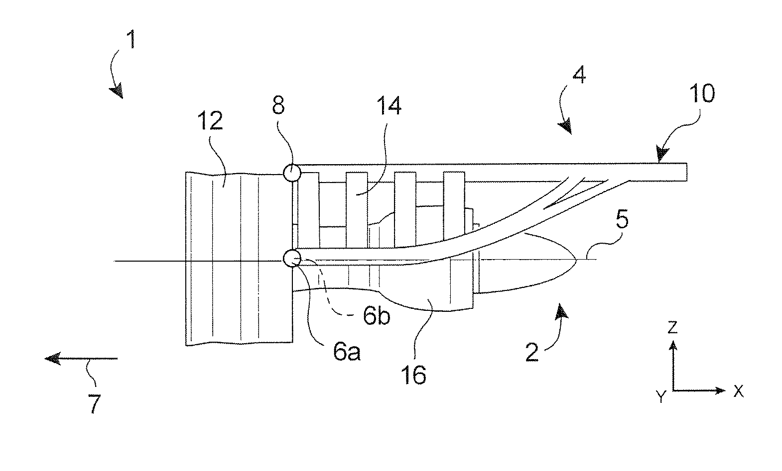
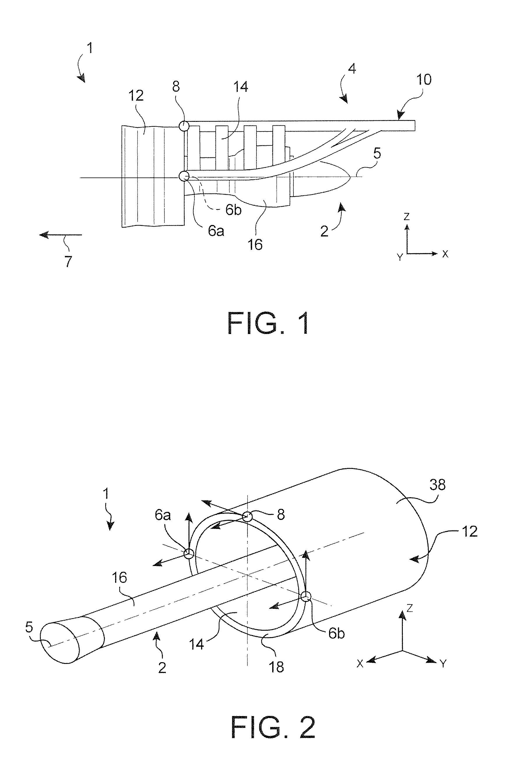
[0048]In reference to FIG. 1, an engine assembly 1 for aircraft according to a preferred embodiment of the present invention is shown, said assembly 1 being intended to be attached underneath the wing of an aircraft (not represented).

[0049]Overall, the engine assembly 1 comprises a turbojet 2, an attachment strut 4, as well as a plurality of engine mounts 6a, 6b, 8 assuring the attachment of the turbojet 2 under said strut 4 (the mount 6b being masked by the mount 6a in this FIG. 1). By way of indication, it is noted that the assembly 1 is intended to be enclosed within a nacelle (not represented), and that the attachment strut 4 comprises another series of mounts (not represented) that make it possible to assure the suspension of said assembly 1 under the wing of the aircraft.

[0050]Throughout the description that follows, by convention, X is taken to mean the direction parallel to a longitudinal axis 5 of the turbojet 2, Y the direction oriented transversally in relation to said sa...


PUM


Abstract

An engine assembly for aircraft including a turbojet, an attachment strut, and a plurality of engine mounts interposed between the attachment strut and the turbojet. Each of the engine mounts is attached to a fan casing of the turbojet.

Description

TECHNICAL FIELD[0001]The present invention concerns, in a general manner, an engine assembly for aircraft, of the type comprising a turbojet, an attachment strut, as well as a plurality of engine mounts interposed between said attachment strut and the turbojet.STATE OF THE PRIOR ART[0002]In a known manner, the attachment strut of such an engine assembly is provided to constitute the liaison interface between an engine, of the turbojet type, and a wing of the aircraft equipped with said assembly. It makes it possible to transmit, to the structure of said aircraft, the stresses generated by its associated engine, and it also allows the routing of the fuel, electrical systems, hydraulics, and air between the engine and the aircraft.[0003]In order to assure the transmission of stresses, the strut comprises a rigid structure, for example of the “box” type, in other words formed by the assembly of spars and lateral panels joined to each other through the intermediary of cross ribs.[0004]A...

Claims


Application Information

Patent Timeline
Patent Type & Authority Patents(United States)
IPC IPC(8): B64D27/00B64D27/26
CPCB64D27/26B64D2027/264
Inventor DIOCHON, LIONELDURAND, JEROME
Owner AIRBUS OPERATIONS (SAS)
Why Eureka
Try Eureka