Professional layout tool

a professional and layout technology, applied in the field of layout tools, can solve the problems of unsuitable for laying out staircase stringers, unsuitable for laying out staircases, awkwardness, time-consuming, etc., and achieve the effect of convenient use and configuration, and easy marking accurate and consistent cut lines

Inactive Publication Date: 2010-06-29
INNOVATIVE DYNAMICS
View PDF30 Cites 13 Cited by
  • Summary
  • Abstract
  • Description
  • Claims
  • Application Information

AI Technical Summary

Benefits of technology

[0004]The inventor has developed an all-in-one combination layout tool that combines and extends the functions of a so-called “speed square” and a “framing square.” It is easy to use and configure for different purposes, including marking center lines for spacing studs, marking rip lines, and marking cut lines for roof rafters and staircase stringers. It is also easier to mark accurate and consistent cut lines with this new layout tool than with prior art devices.
[0006]The locator bar is far more useful than the so-called “layout bar” of the “Big 12 Speed Square.” For one thing, the locator bar can function by itself as a ruler, straight edge, or gauge. Second, the locator bar's “measuring edge” replaces the need for a “lip” on base plate. Either a rounded pivot corner, or the entire “measuring edge” of the locator bar is pressed against a workpiece straight edge in order to position the layout tool for marking or making cut lines. Third, the locator bar can be locked into a selected angular position for very accurate and stable positioning of the layout tool against a workpiece. When configured this way, the layout tool is so stable that it can be used directly as a saw guide - eliminating in many cases the need to mark a cut line. With the tool's locator bar locked into a fixed angular position with respect to the base plate, the tool can be placed against a workpiece while a circular saw is moved against an edge of the base plate, making an accurate angular cut. Fourth, the locator bar can be oriented to mark not only selected cut angles, but also staircase stringer “rise” and “run” cut lines. Fifth, the locator bar can be positioned parallel to the longitudinal edge of the base plate, for easy marking or cutting of “rip” lines. Sixth, the locator bar is longer than the either the width or length dimensions of the base plate. This allows the layout tool to be configured as either an 8-inch by 16-inch framing square or as a 12-inch by 16-inch framing square.
[0007]Furthermore, the rectangular shape of the base plate facilitates accurate angle markings and cut lines along four different edges, and more specifically, along two sets of parallel edges. As illustrated in the accompanying drawings, this configuration provides a number of advantages over prior art tools. One significant advantage is that it the tool does not have to be reconfigured to layout a staircase stringer. Based on the inventor's own experience, it dramatically reduces the time needed to layout staircase stringers—by as much as 90%. It also enables the tool to mark angle cuts from between 0 and 180 degrees, without flipping the tool.
[0008]Part of what makes the present invention so innovative and remarkable is its elegant simplicity. It comprises only a few different parts and is easy to use. But despite its simplicity, the present invention provides numerous advantages over more awkward prior art tools. Those of ordinary skill in the art will appreciate these and other improvements described further below in the detailed description and the accompanying drawings.

Problems solved by technology

But the enlarged lip or flange makes the speed square, without an awkward accessory, unsuitable for laying out staircase stringers.
This particular product, in the inventor's opinion, is awkward, difficult, and time-consuming to use.

Method used


Image

  • Professional layout tool
  • Professional layout tool
  • Professional layout tool

Examples


Embodiment Construction

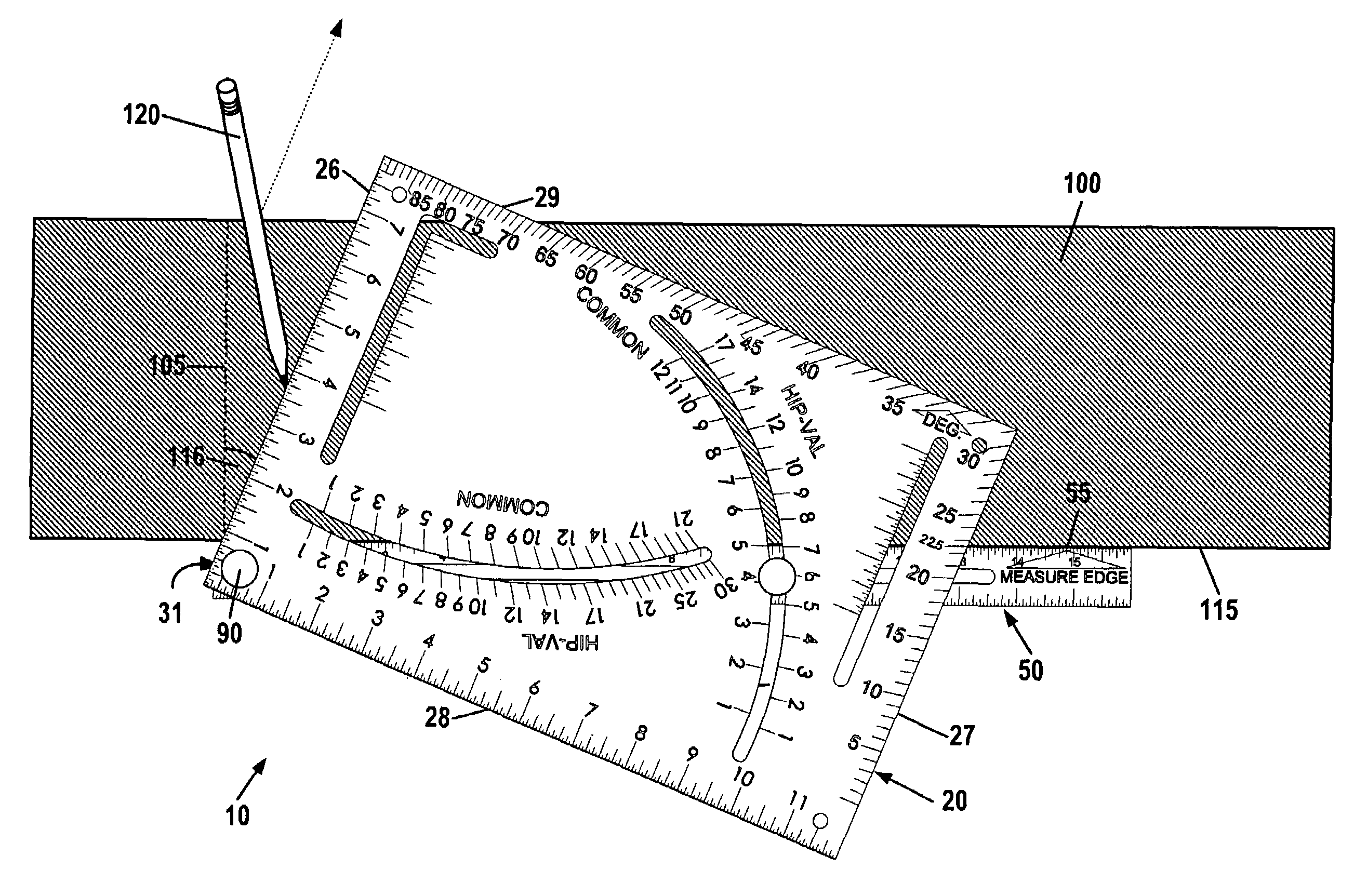
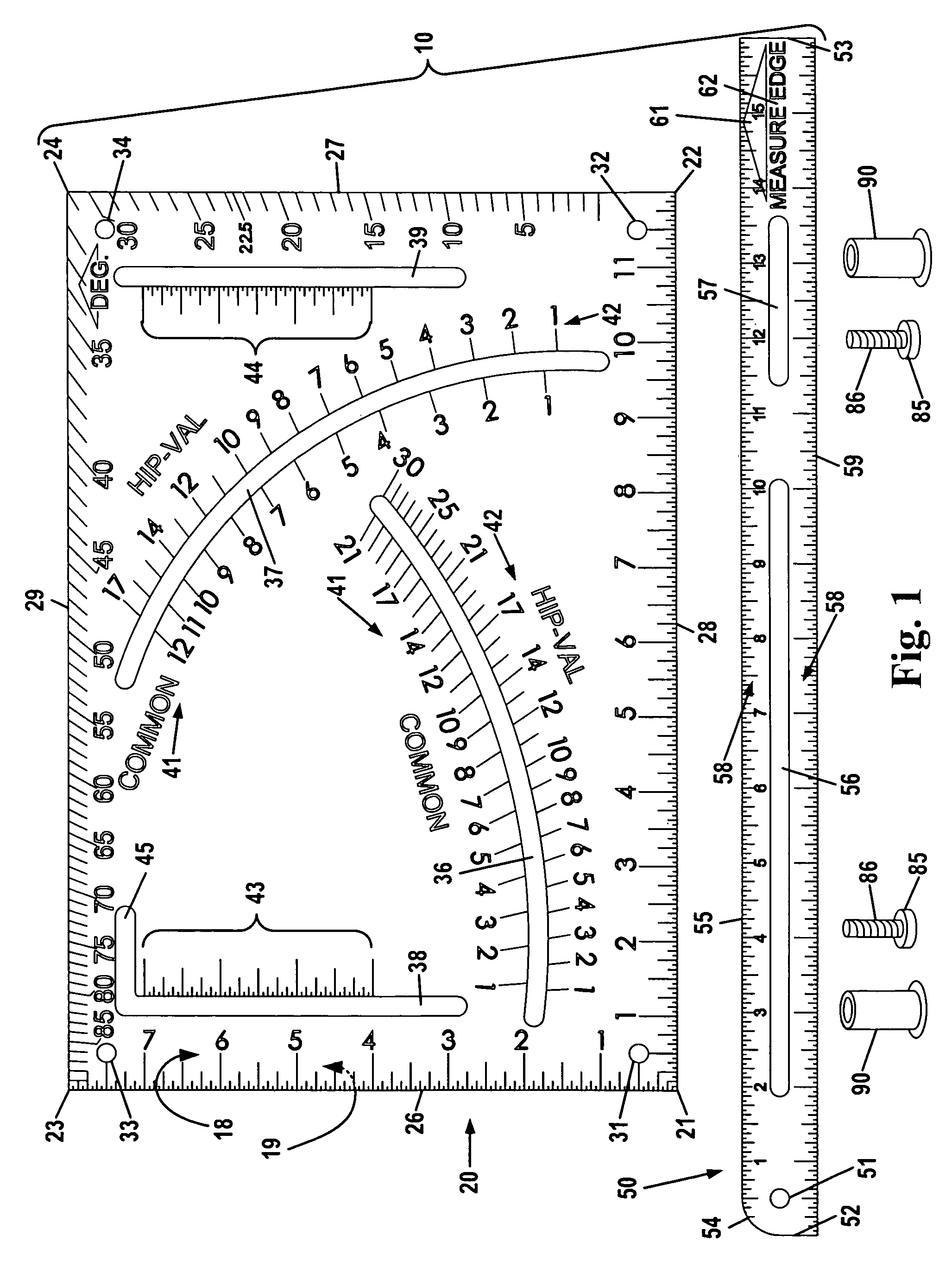
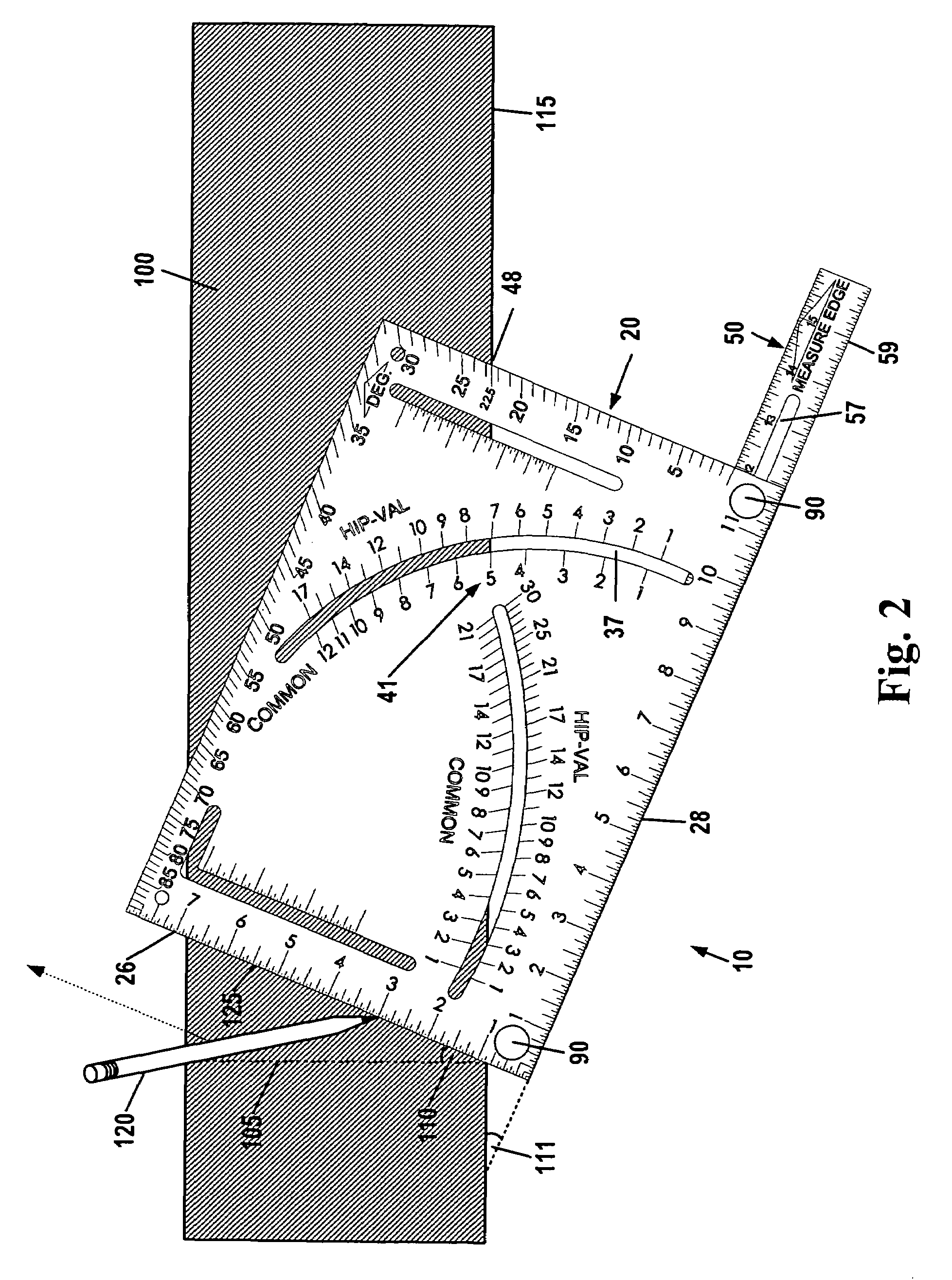
[0020]FIG. 1 illustrates the components of one embodiment of the layout tool 10. Layout tool 10 comprises a rectangular base plate 20, an elongate locator bar 50, two shaft connectors 85 (for example, bolts), and two flange nuts 90. The base plate 20 and locator bar 50 are preferably made of a sturdy, lightweight material, such as aluminum or plastic, for ease of carrying. The locator bar 50 is operable to be pivotally and removably attached to the base plate 20 in a multitude of configurations. The different possible configurations, together with the strategic placement of angular and distance markings on the base plate 20 and the locator bar 50, serve a wide variety of layout needs.

[0021]The elongate locator bar 50 measures 1 inch wide by 16 inches long by 3 / 16 inches thick. It has a latitudinal (i.e., minor-axis) alignment edge 52, a right latitudinal edge 53, a straight measuring edge 55 (also referred to as a “layout edge”), and a longitudinal (i.e., major-axis) alignment edge ...


PUM


Abstract

An all-in-one combination layout tool is provided for marking center lines for spacing studs, marking rip lines, marking cut lines for roof rafters and staircase stringers, and other purposes. The tool comprises a rectangular base plate, an elongate locator bar with a rounded pivot corner, and two connectors to connect the locator bar to the base plate in a variety of configurations. The base plate includes multiple “pivot” points for pivotally connecting the locator bar, two strategically-placed arcuate slots for marking or making angle cuts, and two strategically placed parallel slots for configuring the tool to mark or make rip cuts. Angle markings are provided on two adjacent edges of the base plate, and 1 / 16-inch markings are provided on the opposite adjacent edges. The base plate is planar and has no enlarged flange or lip that would hinder its use in laying out staircase stringers.

Description

FIELD OF THE INVENTION[0001]This invention relates generally to layout tools, and more particularly to so-called “squaring” tools for marking cut lines on workpieces.BACKGROUND OF THE INVENTION[0002]There are several different types of layout tools that have been designed to assist carpenters in framing and construction of roof rafters, staircase stringers, spacing studs, marking rip lines, and the like. Carpenters often use framing squares for laying out staircase stringers and spacing studs. Perhaps the most famous tool for laying out roof rafters is the Swanson Speed Square offered by the Swanson Tool Co. of Frankfort, Ill. The speed square is shaped like a right-angle triangle with an enlarged lip or flange extending along one of the legs of the triangle.[0003]The enlarged lip or flange of the speed square is a critical part of the speed square, for the speed square is positioned on a workpiece by pressing the speed square's lip against the workpiece straight edge. But the enlar...

Claims


Application Information

Patent Timeline
Patent Type & Authority Patents(United States)
IPC IPC(8): B43L7/12B43L7/14
CPCB43L7/005B43L7/14B43L7/12B43L7/027
Inventor O'MORROW, SR., JONATHAN MARK
Owner INNOVATIVE DYNAMICS
Why Eureka
Try Eureka