Double-walled container having supports for positioning the inner and outer walls

a technology of supporting and supporting walls, applied in the direction of containers, liquid dispensing, cosmonautic components, etc., can solve the problem of heavy weight of vessels of this type, and achieve the effect of simplifying the production of vessels

Inactive Publication Date: 2010-06-29
MAGNA STEYR FAHRZEUGTECHN
View PDF74 Cites 23 Cited by
  • Summary
  • Abstract
  • Description
  • Claims
  • Application Information

AI Technical Summary

Benefits of technology

[0007]According to the invention, this is achieved in that inner container and outer container are in each case composed of prepared, fiber-reinforced elements (called “prepregs” in the art) which are in each case wrapped up with a filament and are thereby connected to one another, and in that supports which are also composed of a fiber-reinforced plastic are provided on the inner container for the relative positioning of the inner container with respect to the outer container. In other words: both the outer container and the inner container are each individually composed of fiber-reinforced elements which are each individually held together in such a manner by being wrapped up that they withstand the forces which occur. The supports which are integrated with the inner container in the one or other manner solve the problem of the containers being sufficiently precisely aligned and moveable relative to each other while having different thermal expansions. Owing to the fitting of the supports on the inner container, they can be manufactured precisely in a simple manner and can easily be fitted together. The elements can be assembled in various ways or in a plurality of processing steps to form the particular container.
[0008]In a development of the concept of the invention, inner container and outer container in each case comprise parts which are each individually assembled from prepared, fiber-reinforced elements (for example, prepregs or tubes), which parts adjoin one another along specific joining lines and are consequently wrapped up together with a filament. The filament is generally and advantageously the same as the fibers of the elements themselves. The stepwise building up firstly of the individual parts from prepregs and then of the individual container (inner and / or outer container) from the parts results in them being held together particularly well at very low manufacturing costs.
[0009]For the wrapping up with the filament, it is advantageous to equip the parts of the inner container and of the outer container at the joining lines with mating surfaces suitable for an adhesive bond. The mating surfaces ensure that the parts are fitted together with dimensional accuracy. No particular demands then have to be imposed on the adhesive bond, since it is used predominantly for holding the parts together up until and while they are being wrapped up.
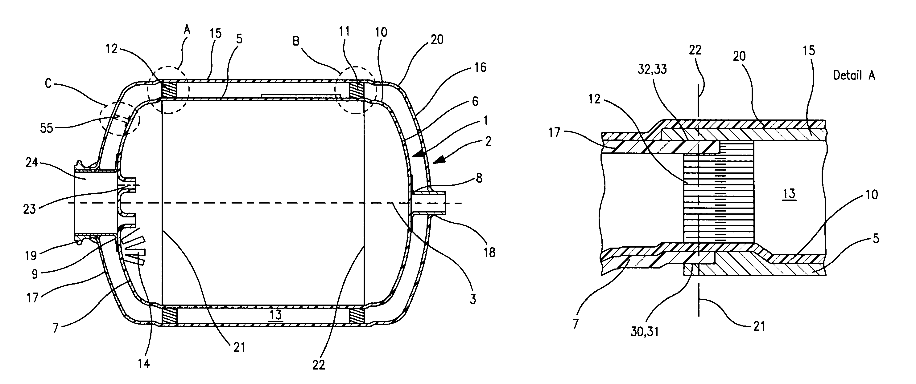
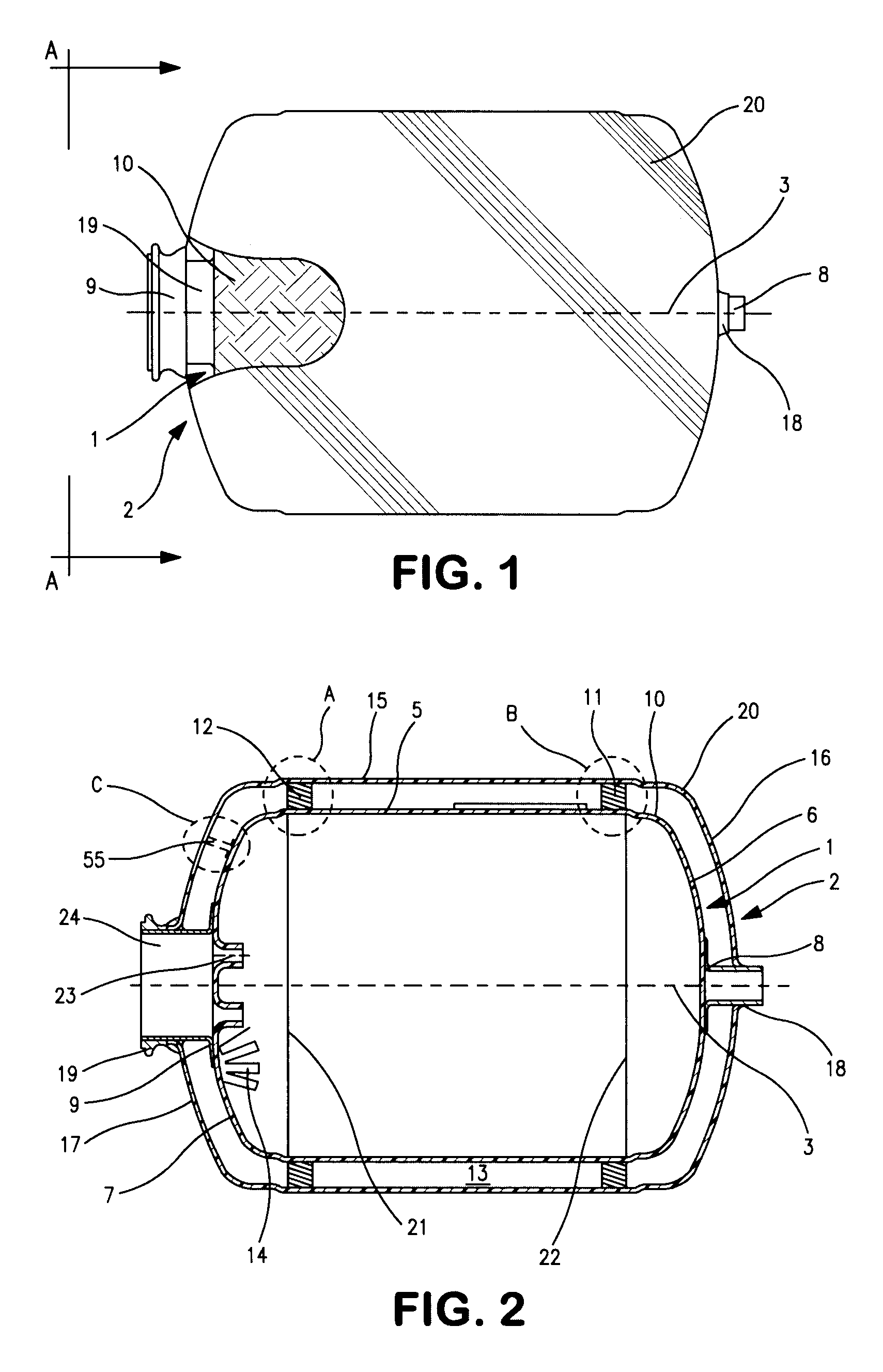
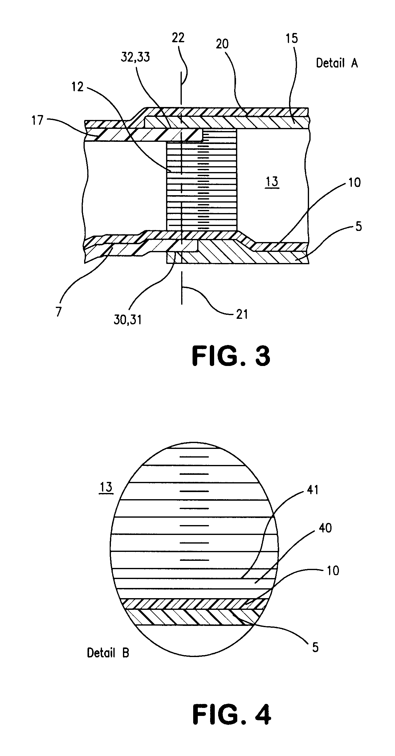
[0013]Although containers built up according to the invention may be of any desired shape as long as their contour does not have any significant concave surface parts, in one preferred embodiment of the invention the vessel is axially symmetrical, comprising a cylindrical, tubular central part and end domes on both sides. Central part and end domes are assembled in each case from prepared, fiber-reinforced elements and are connected to one another at joining lines situated in planes perpendicular to the axis. The central part is then a pre-manufactured tube and the domes are assembled from prepregs. This shape gives rise to particularly favorable stress ratios, also with regard to the vacuum prevailing between inner and outer containers, and is particularly readily suitable for simple and rapid fitting together.
[0014]A further improvement of the force transmission is achieved if, in the case of the inner container, the cylindrical mating surfaces suitable for an adhesive bond are arranged in such a manner that the cylindrical central part overlaps the domes on the inside and, in the case of the outer container, the cylindrical central part overlaps the domes on the outside. This causes the adhesive joints to be subjected to a compressive stress by the vacuum prevailing between inner and outer containers, this increasing their durability, and the subsequent wrapping up under prestress increasing this effect even further.
[0016]As a result, different thermal expansions can be absorbed without asymmetrical displacement between inner and outer containers. For centering and rotating the workpiece during the wrapping-up operation, the domes have a centering slug in the intercepting point with their axis of symmetry. Said centering slug has for this purpose a central, longitudinally directed aperture through which the contents are also equally fed in and removed and other apparatuses can be introduced into the container. In particular the centering slug of the inner container may also be used for centering the latter with respect to the outer container. The line connections into the interior are thus produced at the point at which minimal relative displacements of the two container walls with respect to each other occur and at the point where it is easiest, because of openings which are already present. As a result, the large surfaces of the container walls also remain free for unimpeded wrapping up, which considerably simplifies the production thereof.

Problems solved by technology

Nevertheless, and despite storage approximately at atmospheric pressure, for reasons concerned with the required, precise assignment of inner and outer containers, and, in the case of the vacuum prevailing in between, for reasons concerned with strength and safety, wall thicknesses are required which continue to make vessels of this type extremely heavy.

Method used


Image

  • Double-walled container having supports for positioning the inner and outer walls
  • Double-walled container having supports for positioning the inner and outer walls
  • Double-walled container having supports for positioning the inner and outer walls

Examples


Embodiment Construction

[0023]In FIG. 1 and FIG. 2, a container for cryogenic liquids can be seen, the container comprising an inner container, referred to overall by 1, and an outer container, referred to likewise by 2. The vessel may be of virtually any desired design, for example cuboid or case-shaped, or may also be axially symmetrical, in which case 3 is the axis of symmetry. The inner container 1 comprises a central part 5 and end parts 6, 7. These parts 5, 6, 7 are assembled from fiber-reinforced elements or are themselves such elements. For example, the end parts 6, 7 are assembled in a manner known per se from prepared mats 14 (prepregs) which, for their part, are composed of fibers in a plastic—in particular epoxy resin—matrix. For this purpose, these elements 14 are placed into a mold and then compressed under the action of heat to form the part. The central part 5 is essentially cylindrical and may be produced in the same manner. If the central part is a circular cylinder, then a piece of a tub...


PUM

PropertyMeasurementUnit
axis of symmetryaaaaaaaaaa
temperatureaaaaaaaaaa
weightaaaaaaaaaa

Abstract

A container for cryogenic liquids comprises an inner container and an outer container which are positioned with respect to each other and are thermally decoupled from each other by a vacuum insulation layer. In order, with the lowest possible weight and lowest possible costs in series production, to achieve the best possible heat insulation, the inner container and the outer container are in each case composed of prepared fiber-reinforced elements which are in each case wrapped up together with a filament and are thereby connected to one another, and supports which are also composed of a fiber-reinforced plastic are provided on the inner container for the relative positioning of the inner container with respect to the outer container.

Description

BACKGROUND OF THE INVENTION[0001]The invention relates to vessels for cryogenic liquids, which comprise an inner container and an outer container which are positioned with respect to each other and are thermally decoupled from each other by a vacuum insulation layer. Cryogenic liquids are to be understood as meaning liquefied gases, for example helium, nitrogen or oxygen, but in particular hydrogen. Their temperature in the liquid state is only a few degrees Kelvin. Vessels of this type are used in space travel and will also be used in the future in motor vehicle manufacturing. In these applications, a low weight and best possible heat insulation are important.[0002]When used in motor vehicles using hydrogen as fuel, these requirements are extremely applicable because weight increases the masses to be moved and therefore the consumption of fuel. Added to these, however, are also the typical requirements of everyday use, for example those for increased safety and those for particular...

Claims


Application Information

Patent Timeline
Patent Type & Authority Patents(United States)
IPC IPC(8): F17C1/06F17C1/08F17C1/02F17C3/10F17C3/06F17C3/08
CPCF17C1/06F17C3/08F17C3/06Y10S220/918F17C2201/0104F17C2201/0157F17C2201/054F17C2203/014F17C2203/015F17C2203/0391F17C2203/0629F17C2203/0663F17C2205/0305F17C2209/2154F17C2209/227F17C2221/011F17C2221/012F17C2221/014F17C2221/017F17C2223/0161F17C2223/033F17C2270/0168F17C2270/0194Y02E60/321Y02E60/32F17C1/00
Inventor BRUNNHOFER, KLAUS
Owner MAGNA STEYR FAHRZEUGTECHN
Why Eureka
Try Eureka