
Dispensing wheel alignment devices in vending machine

a technology for dispensing machines and wheels, applied in the field of vending machines, can solve the problems of loss of revenue of vending machine owners, and achieve the effect of eliminating the potential for merchandise jamming, ensuring accurate dispensing wheel alignment, and facilitating and ensuring the dispensing wheel alignmen

Inactive Publication Date: 2010-06-29
CHANG KIL JAE
View PDF13 Cites 12 Cited by
  • Summary
  • Abstract
  • Description
  • Claims
  • Application Information

AI Technical Summary

Benefits of technology

"The present invention is a dispensing wheel alignment device for coin-operated vending machines. The device helps ensure accurate alignment of the dispensing wheel with the drive gear of the coin actuation mechanism, which prevents jamming of merchandise and ensures proper dispensing of the desired amount of merchandise. The device includes a housing, a merchandise storage and dispensing head, and a coin-operated actuation mechanism. It also includes a releasable latch and a detent for securely positioning the dispensing wheel during the dispensing cycle. The technical effect of the invention is to improve the accuracy and efficiency of coin-operated vending machines."

Problems solved by technology

However, it frequently arises that many such persons fail to accurately place the dispensing mechanism at the desired starting position which then results in malfunction of the dispensing mechanism in the form of jamming of the merchandise in the dispensing mechanism or improper dispensing of more merchandise that than desired in response to each coin that is deposited in the coin actuation mechanism such that the owner of the vending machine suffers a loss in revenue as a result.

Method used


Image

  • Dispensing wheel alignment devices in vending machine
  • Dispensing wheel alignment devices in vending machine
  • Dispensing wheel alignment devices in vending machine

Examples


Embodiment Construction

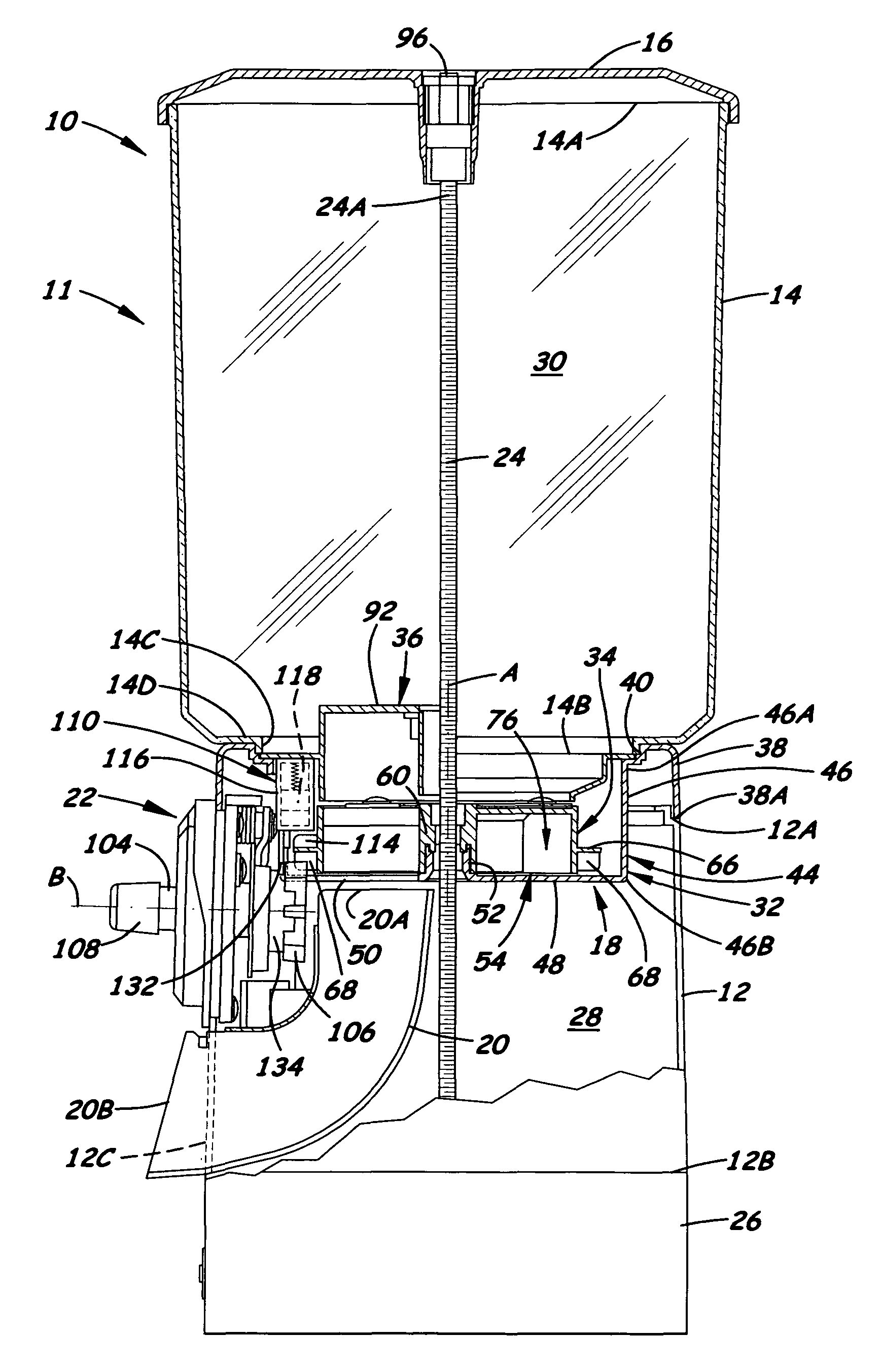
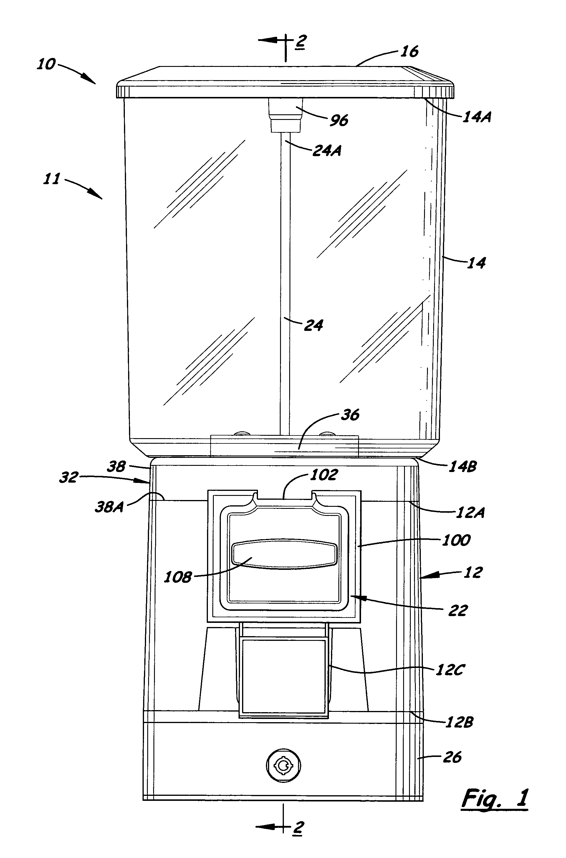
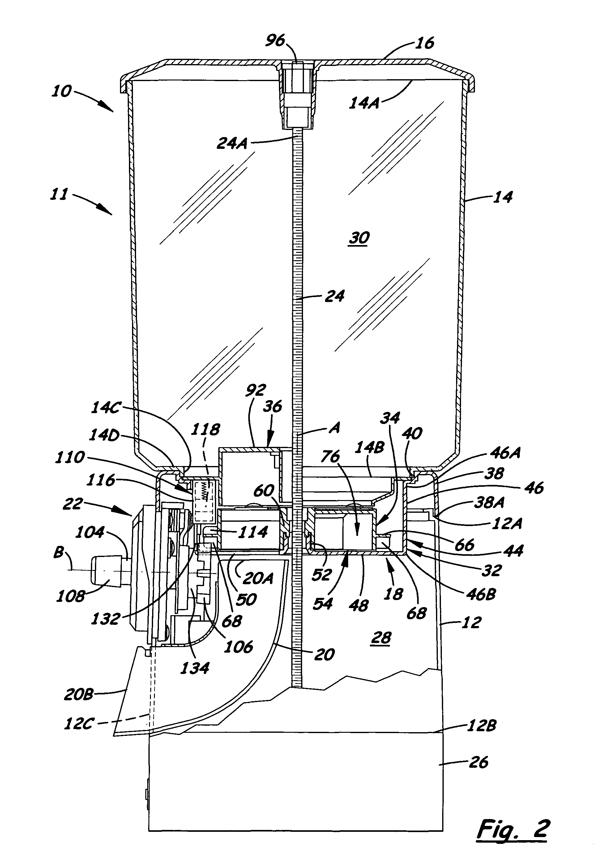
[0028]Referring to the drawings and particularly to FIGS. 1 to 3, there is illustrated a first coin-operated vending machine, generally designated 10, incorporating an exemplary embodiment of a first dispensing wheel alignment device, generally designated 110, of the present invention, being best seen in FIGS. 2 and 6-9. Basically, the first vending machine 10 includes a merchandise storage and dispensing head 11 and a housing 12 supporting the head 11. The head 11 includes a canister 14, a removable cap 16 fittable upon an open upper end 14A of the canister 14, and a dispensing mechanism 18 connected to an open lower end 14B of the canister 14. The vending machine 10 also includes a discharge chute 20 disposed within and supported by the housing 12, a coin-operated actuation mechanism 22 disposed both within and without and supported by the housing 12, and an elongated support rod 24 extendible through and connnectible to the housing 12 and removable cap 16 for lockably interconnec...


PUM


Abstract

A vending machine has a dispensing wheel rotatably mounted on a head with an outer peripheral rim on the wheel having elements displaced angularly from one another in an endless row and radially relative to a central axis of the wheel so as to define a driven gear on the wheel and an alignment device permitting latching of the wheel at, and releasing it from, a desired orientation on the head in a dispensing cycle such that during removing the head from, and remounting it upon, a housing the wheel will be held in a desired relationship with the head in which only given items can pass through the wheel in response to the next deposit of a coin in an actuation mechanism and rotating of a drive gear of the mechanism and driven gear therewith through an actuation cycle corresponding to the dispensing cycle.

Description

[0001]This patent application claims the benefit of U.S. provisional application Nos. 60 / 837,116 and 60 / 878,426, respectively filed Aug. 11, 2006 and Jan. 3, 2007.BACKGROUND OF THE INVENTION[0002]1. Field of the Invention[0003]The present invention generally relates to vending machines and, more particularly, is concerned with dispensing wheel alignment devices in vending machines.[0004]2. Description of the Prior Art[0005]One general type of prior art vending machine, that has been manufactured and sold heretofore by the inventor herein, includes a merchandise storage and dispensing head, a housing supporting the head, a coin-actuated mechanism mounted on and extending into the interior of the housing to where the mechanism operably engages the head, and a coin box disposed in a lower base of the housing below the mechanism for receiving coins from the operation of the coin-actuated mechanism. An upper body of the housing rests on the lower base which closes the bottom of the housi...

Claims


Application Information

Patent Timeline
Patent Type & Authority Patents(United States)
IPC IPC(8): B65H1/00G07F11/10
CPCG07F11/44
Inventor CHANG, KIL JAE
Owner CHANG KIL JAE
Learn More