Method of communicating a command for load shedding of a load control system

a technology of load control system and command, which is applied in the direction of electric controllers, ignition automatic control, instruments, etc., can solve the problems of electrical utility companies that have had difficulty in successfully communicating a command to shed loads to customers, electrical consumers will face a significant increase in their total power costs, and cannot monitor that the customer has actually shed loads

Active Publication Date: 2010-06-29
LUTRON TECH CO LLC
View PDF35 Cites 83 Cited by
  • Summary
  • Abstract
  • Description
  • Claims
  • Application Information

AI Technical Summary

Problems solved by technology

Thus, if an electricity consumer consumes power at a very high rate for only a short period of time, the electricity consumer will face a significant increase in its total power costs.
Electrical utility companies have sought, for many years, to encourage customers to shed load during periods of peak demand, but have been faced with many challenges.
For example, the utility companies have had difficulty successfully communicating a command to shed load to the customers, for example, via radio-frequency (RF) signals or via a modem.
Typically, the electrical utility companies do not have a direct means to know if the customer has actually reduced load, and thus, the electrical utility companies have not been able to monitor that the customer has actually shed loads.
For example, when a radio signal is sent out, there is no way for the power company to tell if a specific customer has actually changed loads to reduce the power consumption.
Further, the electrical utility companies have also had trouble ensuring that the communications with the customer are secure.
The fundamental problem with previous strategies for electronically communicating load shed commands from the electrical utility company to the customers has been that the communications (i.e., RF signals or transmissions via the Internet) with the customer have been initiated at the electrical utility company.
Since the security of computer systems is a major concern of most commercial customers, most customers are wary providing access to their computer systems to outside vendors, such as the electrical utility company.

Method used


Image

  • Method of communicating a command for load shedding of a load control system
  • Method of communicating a command for load shedding of a load control system
  • Method of communicating a command for load shedding of a load control system

Examples


Embodiment Construction

[0029]The foregoing summary, as well as the following detailed description of the preferred embodiments, is better understood when read in conjunction with the appended drawings. For the purposes of illustrating the invention, there is shown in the drawings an embodiment that is presently preferred, in which like numerals represent similar parts throughout the several views of the drawings, it being understood, however, that the invention is not limited to the specific methods and instrumentalities disclosed.

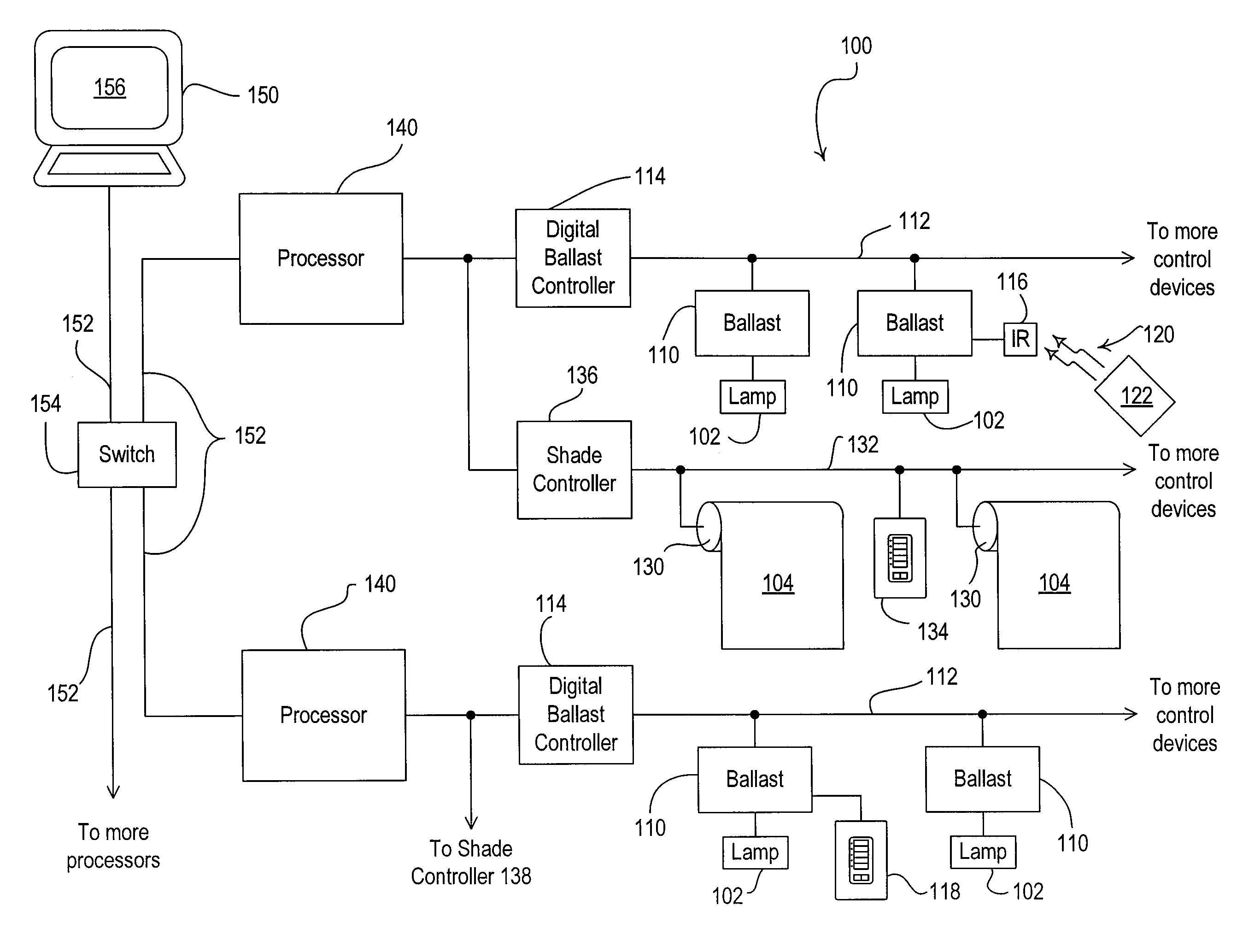
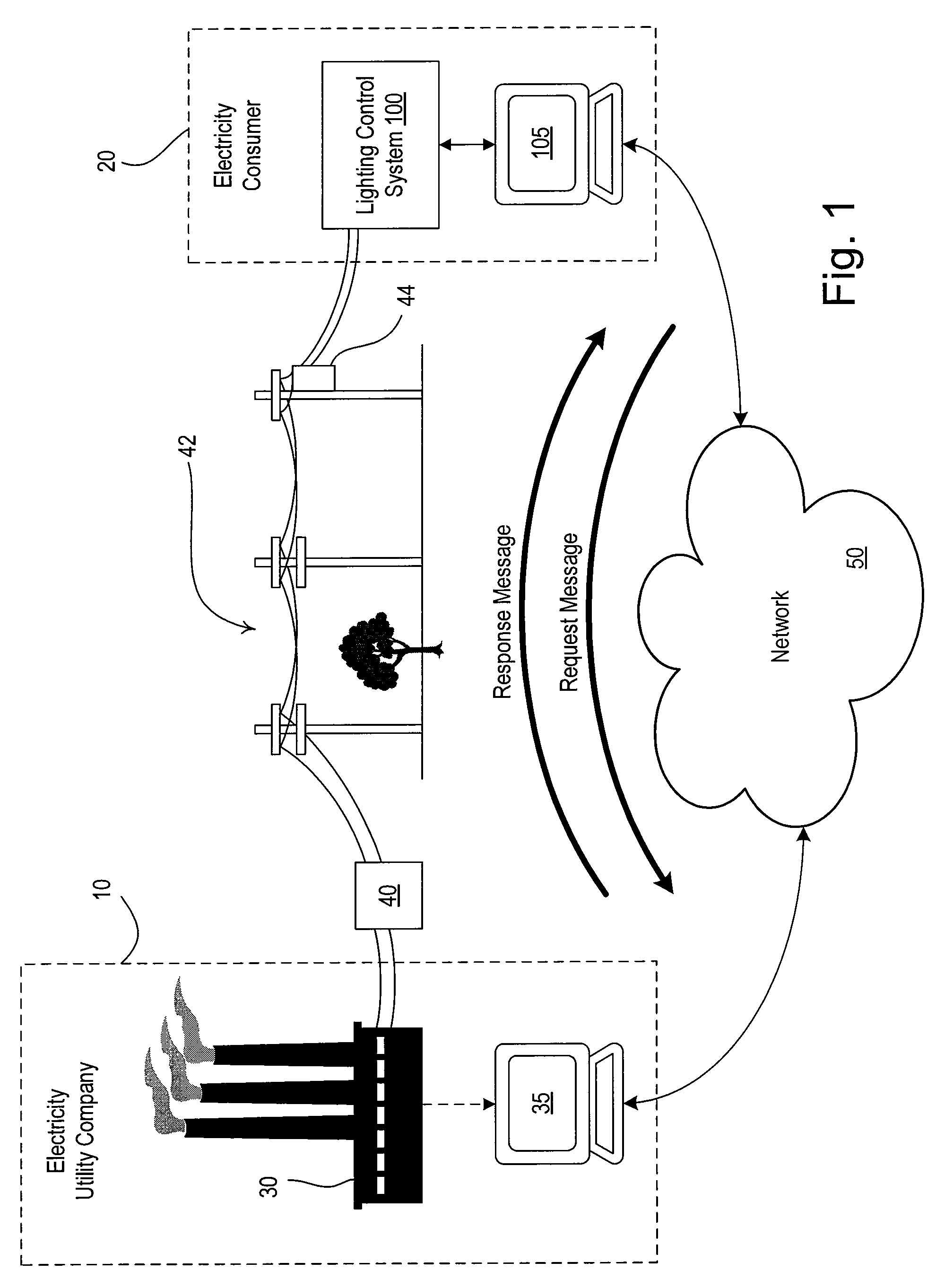
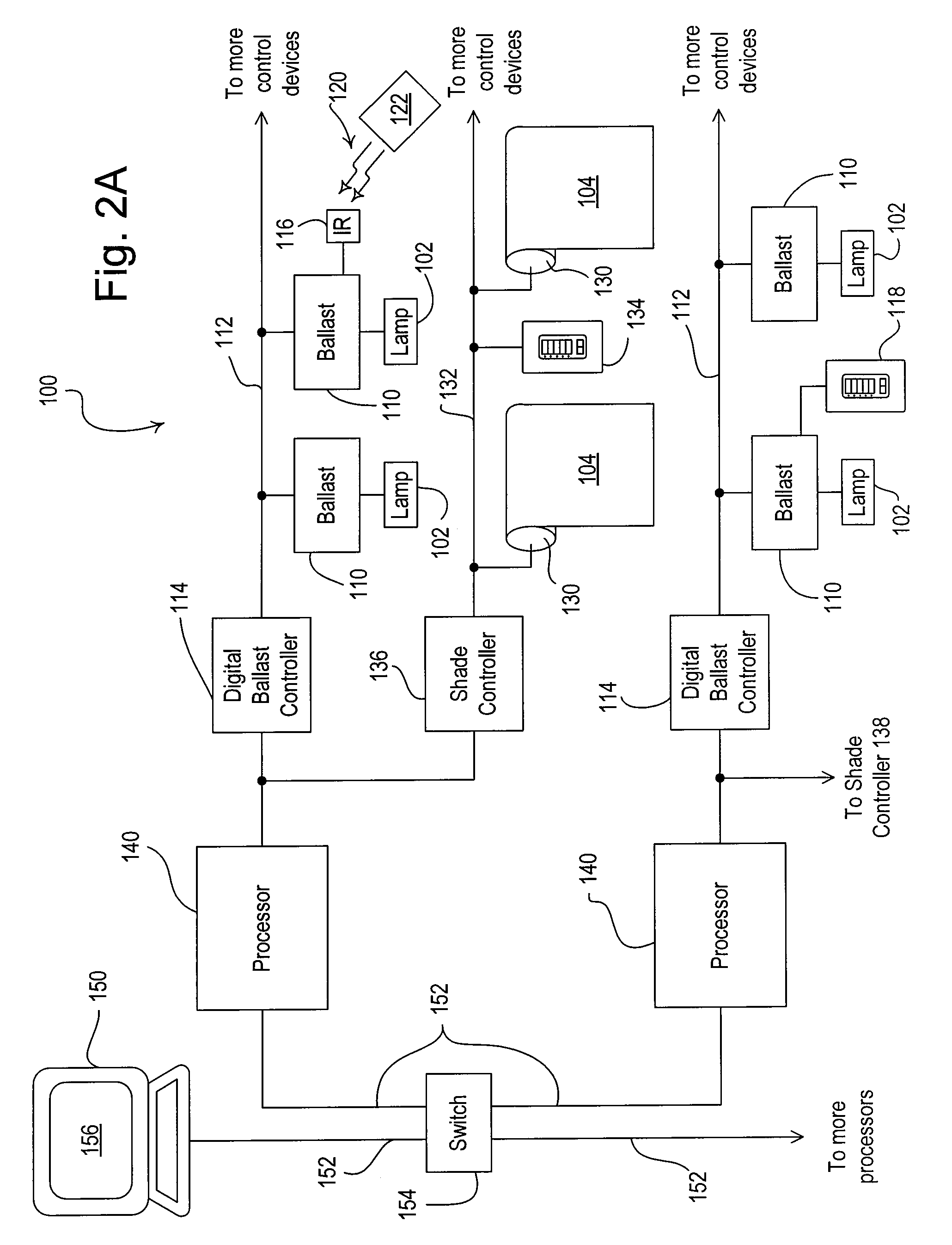
[0030]FIG. 1 is a simplified diagram of an electrical utility company 10 and an electricity customer 20 according to the present invention. The electricity customer 20 comprises a load control system, such as a lighting control system 100, and an internal system server 105, i.e., a personal computer (PC), while the electrical utility company 10 comprises a power generation plant 30 and an external utility server 35, i.e., a PC. The power generation plant 30 is able to provide po...


PUM


Abstract

A system provides for secure communication between an electrical utility company and an electricity customer, such that the customer is able to shed one or more loads in response to a load shed command from the utility company. A system server of the customer periodically connects to a utility server of the utility company using a standard computer protocol, such as Hypertext Transfer Protocol (HTTP). The system server sends a request message via the Internet to the utility server. The request message provides data on the total possible load, the present power consumption, and the present load shed state of the electricity customer. The utility server receives the request message and responds to the request message by transmitting to the system server a response message, which includes a load shed command.

Description

RELATED APPLICATIONS[0001]This application claims priority from commonly-assigned U.S. Provisional Application Ser. No. 60 / 858,524, filed Nov. 13, 2006, entitled METHOD OF LOAD SHEDDING, the entire disclosure of which is hereby incorporated by reference.BACKGROUND OF THE INVENTION[0002]1. Field of the Invention[0003]The present invention relates to a load control system comprising a plurality of load control devices for controlling the amount of power delivered to a plurality of electrical loads from an AC power source, and more particularly, to a lighting control system for shedding lighting loads in response to a command received via a network, such as the Internet.[0004]2. Description of the Related Art[0005]Reducing the total cost of electrical energy is an important goal for many electricity consumers. The customers of an electrical utility company are typically charged for the total amount of energy consumed during a billing period. However, since the electrical utility compan...

Claims


Application Information

Patent Timeline
Patent Type & Authority Patents(United States)
IPC IPC(8): G05D3/12G05D5/00G05D9/00G05D11/00G05D17/00G06F15/16G05B11/01
CPCH05B37/0263H02J3/00H05B47/185
Inventor MURDOCH, JOHN BRUCE
Owner LUTRON TECH CO LLC
Why Eureka
Try Eureka