
Frequency resolved imaging system

a frequency-resolution imaging and target technology, applied in the field of non-invasive optical imaging and target analysis, can solve the problems of limited scan speed, significant alignment and associated signal to noise ratio, and the risk of infection associated with pain and discomfor

Active Publication Date: 2010-07-06
COMPACT IMAGING
View PDF4 Cites 19 Cited by
  • Summary
  • Abstract
  • Description
  • Claims
  • Application Information

AI Technical Summary

Problems solved by technology

In the case of analyzing living entities, such as human tissue, undesirable side effects of invasive analysis include the risk of infection along with pain and discomfort associated with the invasive process.
All of these techniques involve moving parts that have to move a substantial distance, which have limited scan speeds and present significant alignment and associated signal to noise ratio related problems.
Motion occurring within the duration of a scan can cause significant problems in correct signal detection.
If motion occurs within a scan duration, motion related artifacts will be indistinguishable from real signal information in the detected signal, leading to an inaccurate measurement.
Long physical scans, for larger signal differentiation or locating reference areas, increase the severity of motion artifacts.
Non-moving part solutions, include acousto-optic scanning, can be high speed, however such solutions are costly, bulky and have significant thermal control and associated thermal signal to noise ratio related problems.
These, however, have polarization rotation related signal to noise ratio problems and also are physically bulky, are expensive, require relatively high voltage control systems and also have the motion related issues.
These aspects cause conventional OCT systems to have significant undesirable signal to noise characteristics and present problems in practical implementations with sufficient accuracy, compactness and robustness for commercially viable and accurate imaging and analysis devices.

Method used


Image

  • Frequency resolved imaging system
  • Frequency resolved imaging system
  • Frequency resolved imaging system

Examples


Embodiment Construction

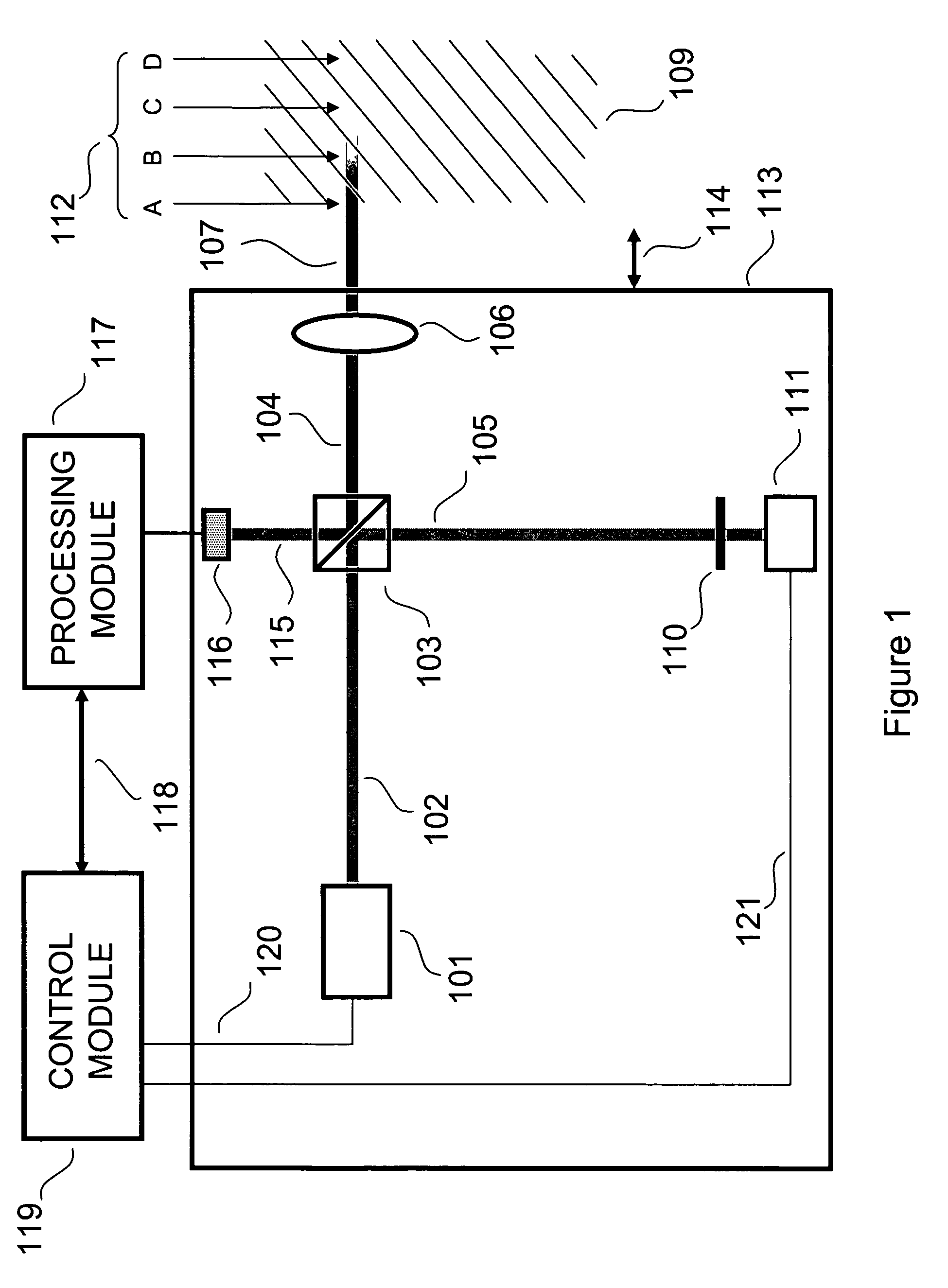
[0015]Conventional optical coherence tomography is based on splitting the output of a broadband optical source into a probe beam and a reference beam and of varying the optical path length of the reference beam to scan the target. This approach has problems and limitations including problems and limitations related to motion occurring within the duration of a scan.

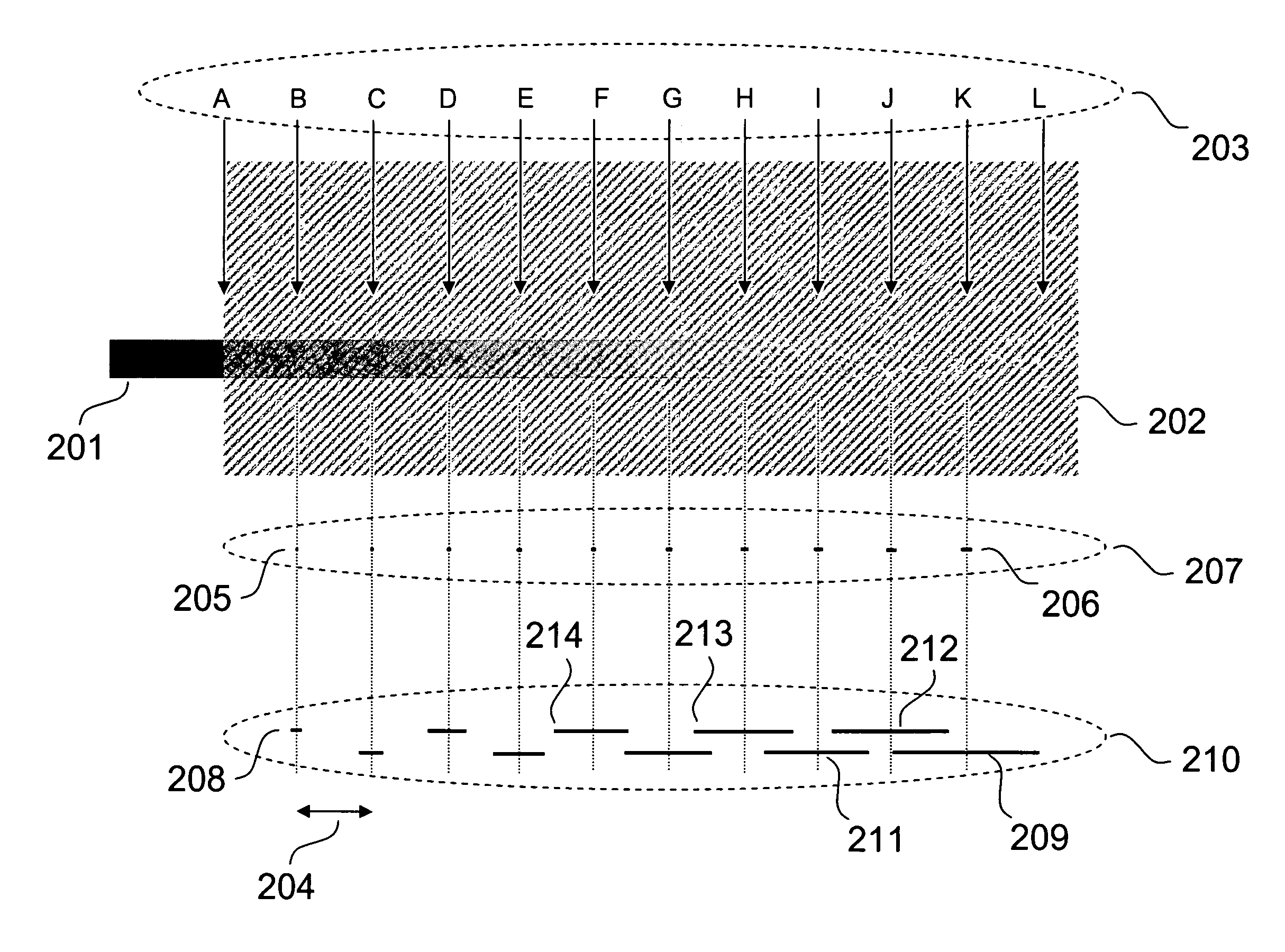
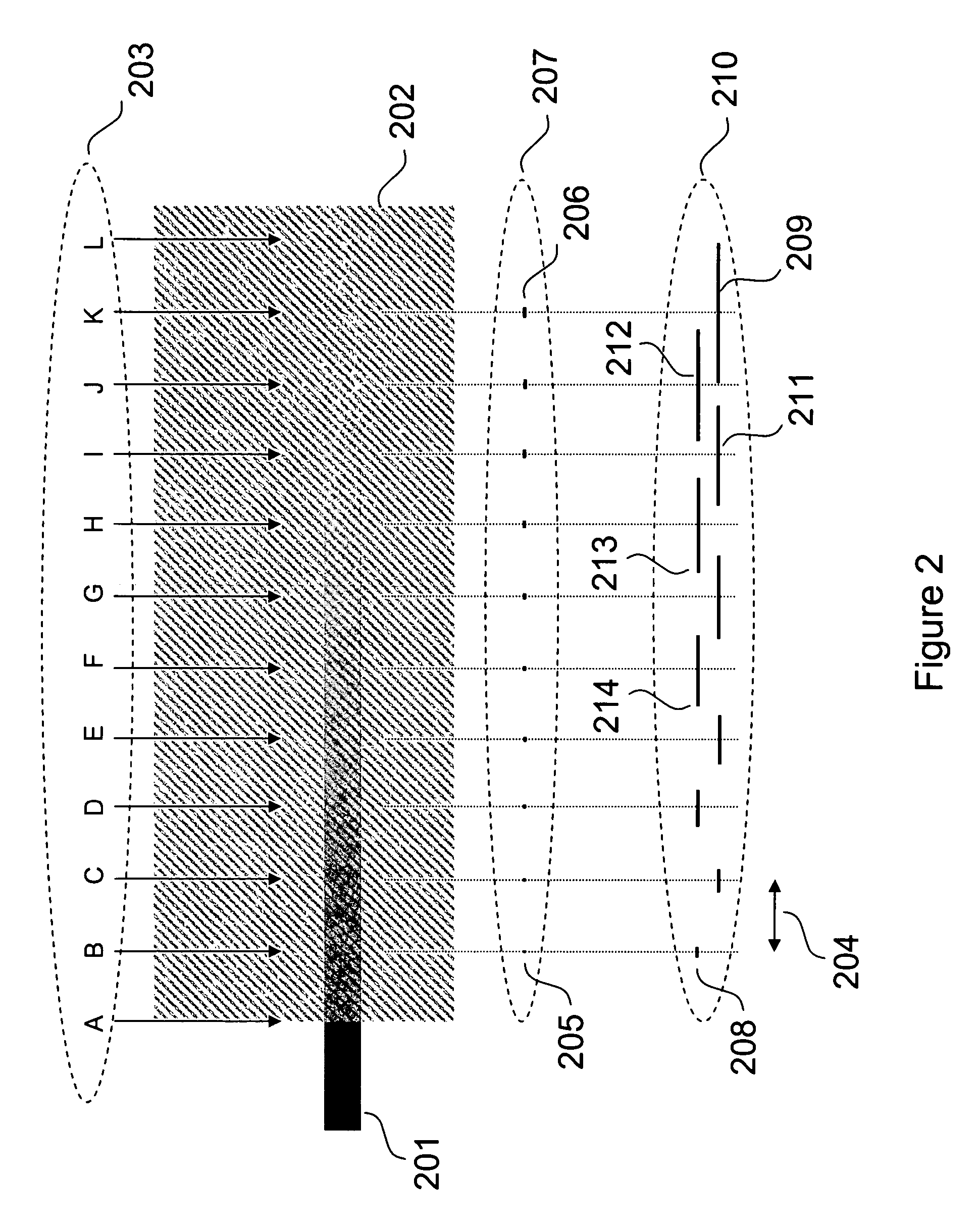
[0016]The present invention is a novel interferometric approach which addresses these problems and limitations by simultaneously acquiring multiple meaningful interferometric signals from multiple depths within the target, thus avoiding relative motion artifacts. With the present invention the interferometric signals from the different depths within the target have different frequency content and thereby can be distinguished from each other and separated by electronic filtering or digital signal processing thereby achieving a scan of a target.

[0017]The invention involves generating composite reference radiation (or a compo...


PUM


Abstract

A non-invasive imaging and analysis system suitable for non-invasive imaging and analysis of defects or malignant aspects of targets such as cancer in skin or human tissue and suitable for measuring concentrations of specific components, such as blood glucose concentration includes an optical processing system which generates a probe and composite reference beam. The system also includes a means for applying the probe beam to the target to be analyzed and modulates at least some of the components of the composite reference beam such that signals with different frequency content are generated. The system combines a scattered portion of the probe beam and the composite beam interferometrically to simultaneously acquire information from multiple depths within a target. It further includes electronic control and processing systems.

Description

CROSS REFERENCES TO RELATED APPLICATIONS[0001]This application, is a continuation in part of U.S. utility application Ser. No. 11 / 025,698 filed on Dec. 29, 2004 now U.S. Pat. No. 7,526,329 titled “Multiple reference non-invasive analysis system”, the contents of which are incorporated by reference as if fully set forth herein. This application, claims priority from provisional application Ser. No. 60 / 602,913 filed on Aug. 19, 2004 titled “Multiple reference non-invasive analysis system”. This application also relates to U.S. utility application Ser. No. 10 / 949,917 filed on Sep. 25, 2004 titled “Compact non-invasive analysis system”, the contents of which are incorporated by reference as if fully set forth herein.FIELD OF THE INVENTION[0002]The invention relates to non-invasive optical imaging and analysis of targets and in particular to non-invasive analysis of defects or malignant aspects of targets such as cancer in skin or human tissue. This invention also relates to quantitative...

Claims


Application Information

Patent Timeline
Patent Type & Authority Patents(United States)
IPC IPC(8): A61B5/1455A61B6/00
CPCA61B5/0059A61B5/0066A61B5/14532A61B5/1455
Inventor HOGAN, JOSHUA NOEL
Owner COMPACT IMAGING
Learn More