Power stealing for a thermostat using a TRIAC with FET control

a triac and thermostat technology, applied in the direction of process and machine control, emergency protective circuit arrangement, electric vehicles, etc., can solve the problem of significant battery drain, and achieve the effect of improving power th

Inactive Publication Date: 2010-07-13
CARRIER CORP
View PDF11 Cites 130 Cited by
  • Summary
  • Abstract
  • Description
  • Claims
  • Application Information

AI Technical Summary

Benefits of technology

[0006]An electronic thermostat circuit has improved power stealing for controlling an AC control device. The circuit comprises a source of AC control power coupled to an electronic switch means having an electronic switch means control input. The electronic switch means controls the AC control device. A diode bridge means has an AC connection and a DC connection. The AC connection is electrically coupled to the electronic switch means control input. The diode bridge controls the electronic switch means by a DC control signal applied to the diode bridge means DC connection. An amplifier means has an on state and an off state. The amplifier means is electrically coupled to the diode bridge means DC connection. The amplifier means has an amplifier input for controlling the state of the amplifier and an amplifier output for generating the DC control signal. An isolated gate FET means is electrically coupled to the amplifier input for controlling the state of the amplifier. The isolated gate FET means is further electrically coupled to a digital input signal. The digital input signal controls the state of the DC amplifier means. The isolated gate FET means is powered by the current derived from the source of AC control power by power stealing. The digital signal controls the state of the AC control.

Problems solved by technology

One problem is to minimize the amount of power stealing so as to avoid a false switching of the device being controlled by that line.
Another problem is that even with power stealing, there can still be significant battery drain by the output electronic circuits in the thermostat that controls the switching of each device controlled by the thermostat.

Method used


Image

  • Power stealing for a thermostat using a TRIAC with FET control
  • Power stealing for a thermostat using a TRIAC with FET control
  • Power stealing for a thermostat using a TRIAC with FET control

Examples


example

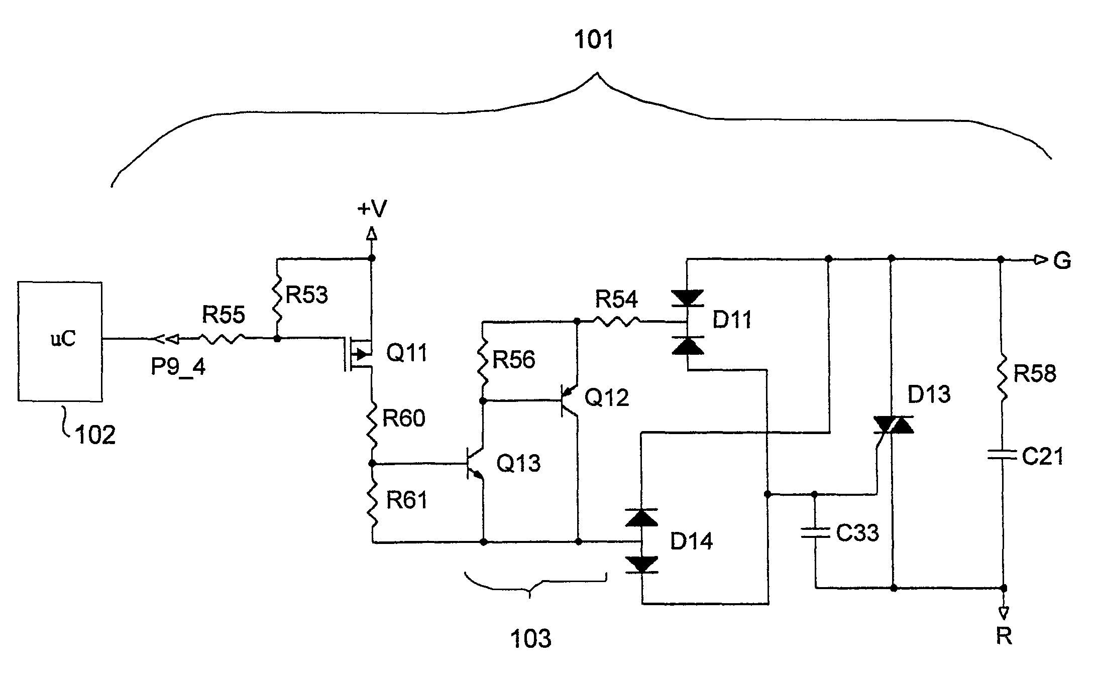
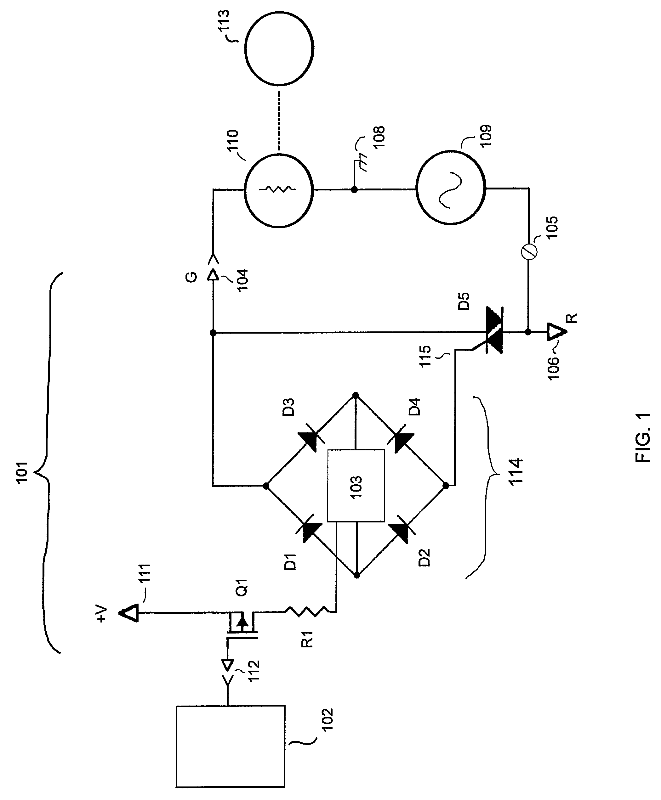
[0021]FIG. 4 shows an advantageous embodiment of the inventive circuit topology 101 of FIG. 1. It is to be understood that these component values and component types are merely exemplary values and types that were used in a particular embodiment of the inventive circuit topology. For example, any suitable P channel enhancement mode FET can be used as Q11, or any suitable NPN or PNP transistors can be used as Q12 and Q13. Similarly, the values of resistors and capacitors can be varied in other embodiments.

[0022]It is to be noted that a particular embodiment of the exemplary output circuit topology 101 of FIG. 4 has the following component values:

Q11 BSS84, P channel enhancement mode FET

Q13 MMBTA05LT1

Q12 MMBTA55LT1

D11 MMBD1204

D14 MMBD1205

D13 T405-600B

R53 2.2 Meg Ohms

R54 2.2 kilo Ohms

R55 1 Meg Ohms

R60 100 kilo Ohms

R61 150 kilo Ohms

R56 4.7 kilo Ohms

R58 150 Ohms

C21, C33 0.1 micro Farads

[0023]The operation of the circuit of FIG. 4 when the components have the particular values as set fort...


PUM


Abstract

An electronic thermostat circuit has improved power stealing for controlling an AC control device. The circuit comprises a source of AC control power coupled to an electronic switch means having an electronic switch means control input. The electronic switch means controls the AC control device. The diode bridge controls the electronic switch means by a DC control signal applied to the diode bridge means DC connection. The amplifier means has an amplifier input for controlling the state of the amplifier and an amplifier output for generating the DC control signal. An isolated gate FET means is electrically coupled to the amplifier input for controlling the state of the amplifier. The isolated gate FET means is powered by the current derived from the source of AC control power by power stealing. The digital signal controls the state of the AC control.

Description

FIELD OF THE INVENTION[0001]This invention relates to an electronic thermostat output control circuit to improve power stealing, and more particularly to a circuit topology to minimize the power needed to control thermostat outputs.BACKGROUND OF THE INVENTION[0002]Electronic thermostats can be used to control the temperature in a building space as part of the building's heating, ventilation and air conditioning (“HVAC”) system. Thermostats typically receive temperature information from one or more temperature sensors. While simple thermostats react to the sensor inputs using only analog circuits, most modern thermostats run a microcontroller program or algorithm. The algorithm determines when the various devices controlled by the thermostat should be turned on or off based on the temperature data. Thus, thermostats function as switches to control devices such as furnaces, blowers, motors, and compressors. Rather than switching the full device load current, the controlled devices are...

Claims


Application Information

Patent Timeline
Patent Type & Authority Patents(United States)
IPC IPC(8): G05D23/00
CPCH02M5/2576
Inventor SORG, SCOTT A.COMERFORD, TIMOTHY N.MEANS, DONALD R.
Owner CARRIER CORP
Why Eureka
Try Eureka