Voltage controlled oscillator for controlling phase noise and method using the same

a voltage control and phase noise technology, applied in the field of phase noise control, can solve problems such as difficulties in the circuit of the oscillator, and achieve the effect of reducing phase nois

Inactive Publication Date: 2010-07-13
SAMSUNG ELECTRONICS CO LTD
View PDF12 Cites 2 Cited by
  • Summary
  • Abstract
  • Description
  • Claims
  • Application Information

AI Technical Summary

Benefits of technology

[0014]The amplifier may amplify the value obtained by performing the n-th differentiation on the transconductance component of each first output signal by adjusting a bias voltage applied to the amplifier. The bias voltage may be a voltage at which the first output signals intersect with each other, where the first output signals have predetermined slopes.
[0019]According to another aspect of the present invention, there is provided a method of improving phase noise in a VCO. The method includes generating first output signals having an oscillation frequency corresponding to a supply voltage; amplifying a value obtained by performing n-th (n being a natural number) differentiation on a transconductance component of each first output signal; and outputting second output signals corresponding to the first output signals. Each second output signal includes the amplified value of the corresponding first output signal. The n-th differentiation may be a secondary differentiation.
[0021]According to yet another aspect of the present invention there is provided a method of reducing phase noise in a VCO. The method includes generating a first output signal having an oscillation frequency corresponding to a supply voltage; performing secondary differentiation on a transconductance component of the first output signal to obtain a differentiation value; amplifying the differentiation value; and outputting a second output signal corresponding to the first output signal. The second output signal includes the amplified differentiation value. Also, the second output signal may have a steeper slope than the first output signal, and may have a wave form approximating a square wave. Amplifying the differentiation value may include adjusting a bias voltage.

Problems solved by technology

However, since the CMOS circuits generally have poor noise characteristics, a low breakdown voltage, and a low gain, CMOS circuits present some difficulties notwithstanding their high integration and efficient productivity.

Method used


Image

  • Voltage controlled oscillator for controlling phase noise and method using the same
  • Voltage controlled oscillator for controlling phase noise and method using the same
  • Voltage controlled oscillator for controlling phase noise and method using the same

Examples


Embodiment Construction

[0032]The present invention will now be described more fully with reference to the accompanying drawings, in which exemplary embodiments of the invention are shown. The invention, however, may be embodied in various different forms, and should not be construed as being limited only to the illustrated embodiments. Rather, these embodiments are provided as examples, to convey the concept of the invention to one skilled in the art. Accordingly, known processes, elements, and techniques are not described with respect to some of the embodiments of the present invention. Throughout the drawings and written description, like reference numerals will be used to refer to like or similar elements.

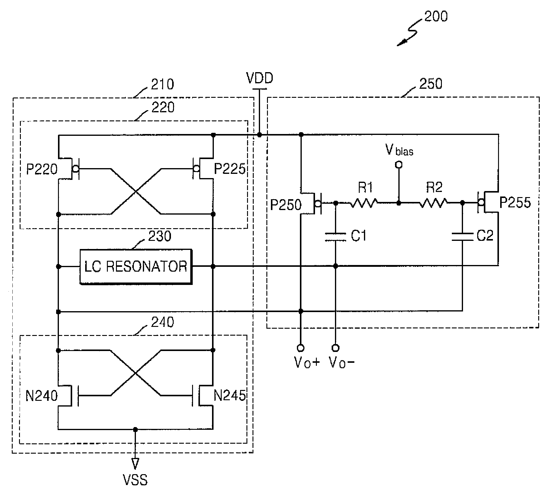
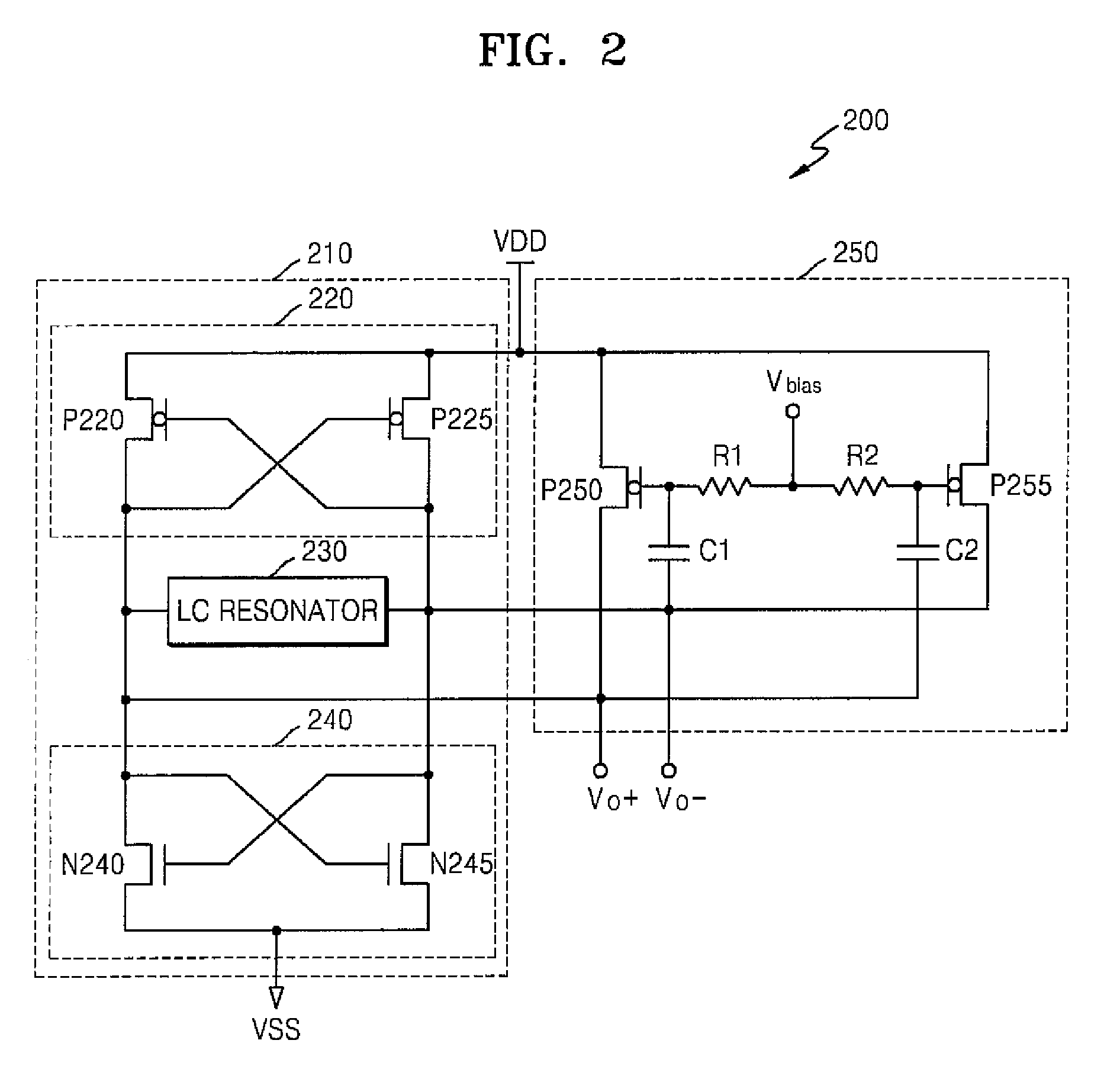
[0033]Embodiments of the present invention provide a Voltage Controlled Oscillator (VCO) for controlling phase noise by outputting an output signal having a waveform similar to or approximating a square wave. Embodiments of the present invention also provide a method of controlling phase noise using t...


PUM


Abstract

A voltage controlled oscillator (VCO) includes a VCO unit having multiple VCO unit output terminals and an amplifier having multiple amplifier output terminals respectively connected to the VCO unit output terminals. The VCO unit generates first output signals having an oscillation frequency corresponding to a supply voltage. The amplifier amplifies a value obtained by performing n-th differentiation on a transconductance component of each first output signal (n being a natural number). Second output signals, corresponding to the first output signals, are output through the amplifier output terminals. Each second output signal includes the amplified value of the corresponding first output signal.

Description

CROSS-REFERENCE TO RELATED PATENT APPLICATION[0001]A claim of priority is made to Korean Patent Application No. 10-2007-0002174, filed on Jan. 8, 2007, the subject matter of which is hereby incorporated by reference.BACKGROUND OF THE INVENTION[0002]1. Field of the Invention[0003]The present invention relates to phase noise control, and more particularly, to a Voltage Controlled Oscillator (VCO) for controlling phase noise and a method of controlling the phase noise by using the VCO.[0004]2. Description of the Related Art[0005]A Voltage Controlled Oscillator (VCO) is an apparatus for outputting a desired oscillation frequency using a supply voltage, and is widely used, for example, in mobile communication terminals and the like. For example, the VCO functions as a local oscillator, which may be used in a Phase Locked Loop (PLL) module of a mobile communication device to assign channels and to convert a frequency into a Radio Frequency (RF) or an Intermediate Frequency (IF).[0006]Comp...

Claims


Application Information

Patent Timeline
Patent Type & Authority Patents(United States)
IPC IPC(8): H03K3/282
CPCH03B5/1228H03B5/1212H03B5/1243H03B5/1218H03B5/1225A47G9/0223A47G9/083A47G9/1072
Inventor KIM, WOONYUN
Owner SAMSUNG ELECTRONICS CO LTD
Why Eureka
Try Eureka