Optical fiber splitter module and fiber optic array therefor

a technology of optical fiber and fiber optic array, which is applied in the direction of optical light guides, fibre mechanical structures, instruments, etc., can solve the problems of limiting the installation of optical fibers, one expensive component of the network, and prohibiting the cost of installing optical fibers closer to the subscribers' homes

Active Publication Date: 2010-07-13
CORNING OPTICAL COMM LLC
View PDF10 Cites 61 Cited by
  • Summary
  • Abstract
  • Description
  • Claims
  • Application Information

AI Technical Summary

Problems solved by technology

However, installing the optical fibers closer to the subscribers' homes can be cost prohibitive.
Currently, one expensive component of the network that is limiting the installation of the optical fibers closer to the home is the optical splitter.

Method used


Image

  • Optical fiber splitter module and fiber optic array therefor
  • Optical fiber splitter module and fiber optic array therefor
  • Optical fiber splitter module and fiber optic array therefor

Examples


Embodiment Construction

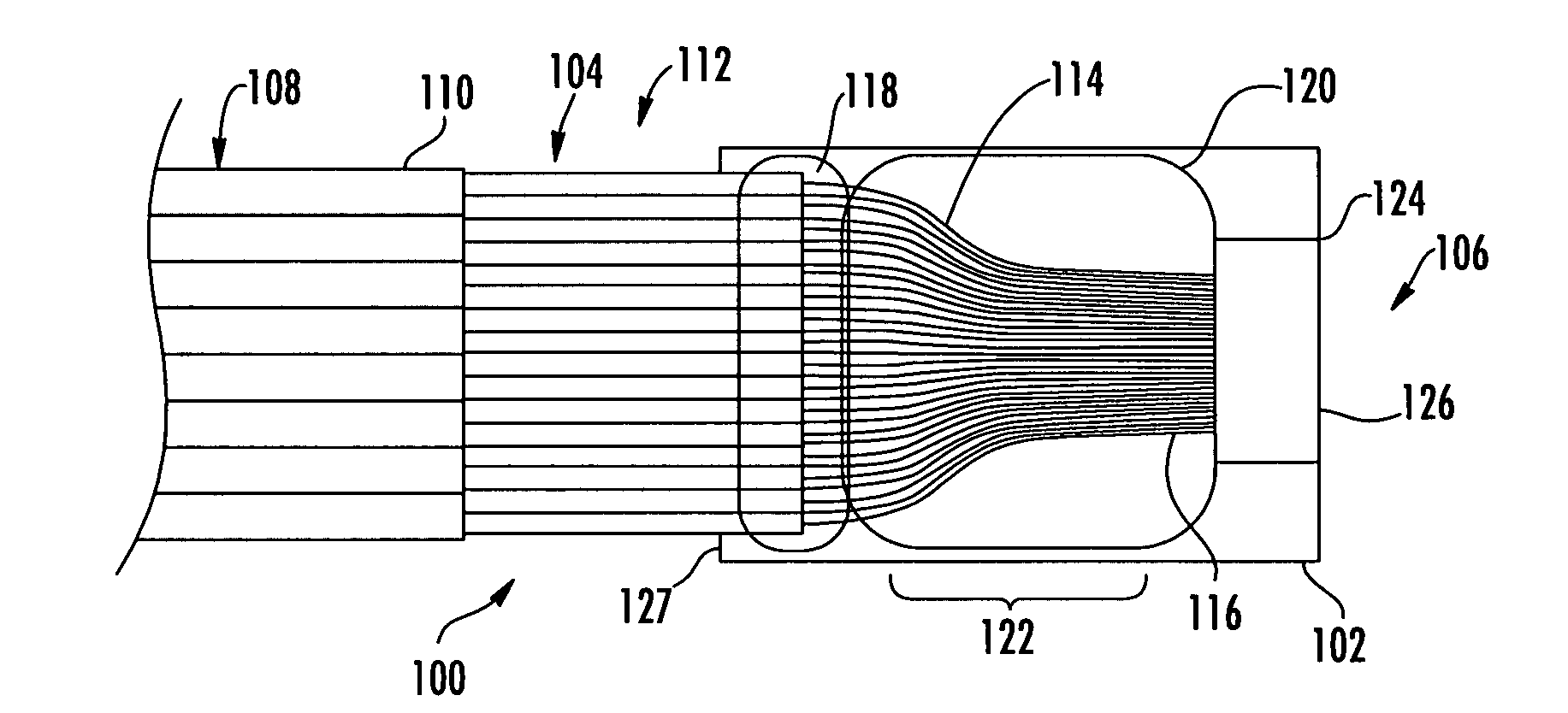
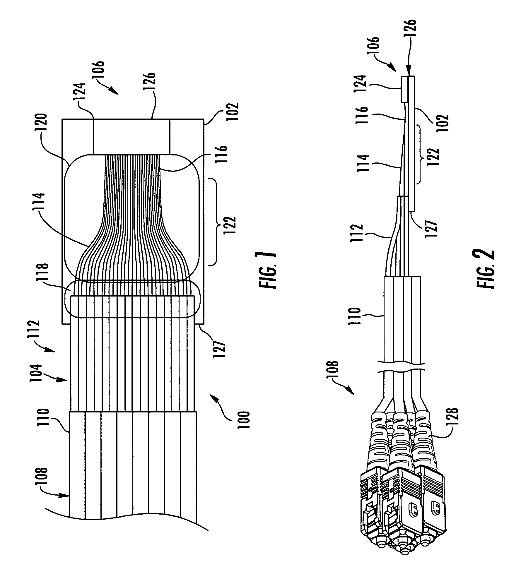
[0027]Reference will now be made in detail to exemplary embodiments of the invention, examples of which are described herein and shown in the accompanying drawings. Whenever practical, the same reference numerals are used throughout the drawings to refer to the same or similar parts or features. One embodiment of an optical fiber array according to the present invention is illustrated in FIGS. 1 and 2 and is designated generally throughout the following detailed description by the reference numeral 100.

[0028]The optical fiber array 100 has a base member 102 to which the optical fibers 104 are attached. The base member 102 is preferably made of glass, but any material suitable for the purpose may be used. The optical fibers 104 have a first end 106 and a second end 108. The second end 108 of the optical fibers 104 have the largest diameter, and in FIGS. 1 and 2, are buffered optical fibers having an outer diameter of 2 mm. As defined herein, the terms “optical fiber” and “optical fib...


PUM


Abstract

An optical fiber splitter has a higher density fiber optic array that allows for smaller packaging. The optical fibers that extend from the optical fiber splitter have one end connectorized and their spacing at the other end reduced, thereby eliminating components that were heretofore required. A method of making the fiber optic array includes interleaving the optical fibers to reduce the overall dimensions of the fiber optic array and the fiber optic splitter. A tool is used to reduce the spacing of the optical fibers in the fiber optic array.

Description

[0001]This application is a continuation-in-part of U.S. application Ser. No. 11 / 171,915, filed on Jun. 30, 2005 now abandoned, the contents of which are hereby incorporated herein by reference.BACKGROUND OF THE INVENTION[0002]1. Field of the Invention[0003]The present invention relates generally to an optical fiber splitter module with a higher density fiber optic array that allows for smaller packaging of the fiber optic array and splitter. The optical fibers that extend from the optical fiber splitter module have one end connectorized and the spacing at the second end reduced, thereby eliminating components that were heretofore required and made the splitter modules large and cumbersome.[0004]2. Technical Background[0005]Communications networks, and particularly high bandwidth optical networks, are being installed closer to the subscribers' homes. However, installing the optical fibers closer to the subscribers' homes can be cost prohibitive. Therefore, the network owners are con...

Claims


Application Information

Patent Timeline
Patent Type & Authority Patents(United States)
IPC IPC(8): G02B6/00
CPCG02B6/2804G02B6/368G02B6/3636G02B6/3664
Inventor SARAVANOS, COSTASMAKRIDES-SARAVANOS, ELLISZENTESI, OTTO I.MILLER, WILLIAM J.
Owner CORNING OPTICAL COMM LLC
Why Eureka
Try Eureka