Portable dispensing systems

a portable, self-contained technology, applied in the direction of instruments, liquid transfer devices, single-unit apparatuses, etc., can solve the problem of limited product range that the new system can store and dispense, and achieve the effect of being convenient and disposabl

Inactive Publication Date: 2010-07-20
THE X GROUP
View PDF8 Cites 2 Cited by
  • Summary
  • Abstract
  • Description
  • Claims
  • Application Information

AI Technical Summary

Benefits of technology

[0011]In certain embodiments, the actuating mechanism includes one or more actuating arms having an angled face; and the device further includes a pump mount connected to the pump having a wedge surface that is arranged to contact the angled face of the actuating arm. In this arrangement, pressure on a portion of the actuating mechanism in a first direction causes the one or more actuating arms to move, causing the angled face to press against the wedge surface, causing the wedge surface and the pump to move in a second direction, and causing the pump to expel fluid from the reservoir through the nozzle and out of the device through the orifice.
[0015]The new dispensing systems are relatively inexpensive and disposable and can be used for many different products and for many different occasions, and are thus ideal for mass-market distribution. Metal versions of the same designs can be made to be more durable and non-disposable.
[0017]The new devices have clear advantages over similar size sampling type dispensers, offering their users the convenience of multiple uses in metered doses in the form of a spray, mist, stream, or drops. The device can be personally stored between uses. In addition, the new devices offer a scalable design that can be altered for both functional and ornamental presentation.

Problems solved by technology

The range of products that the new systems can store and dispense is limited only by their size and internal pump design(s).

Method used


Image

  • Portable dispensing systems
  • Portable dispensing systems
  • Portable dispensing systems

Examples


second embodiment

[0068]FIG. 15A shows an alternative embodiment of the portable dispensing device. FIG. 15B shows an “exploded” view of this device. This second embodiment of the device includes a housing 100 with a base 102, and a lid 104. Dispensing button 106 is inserted into housing 100 and protrudes through lid 104. Button 106 has a flange 107 that prevents it from being pulled out of the device through opening 105 in lid 104.

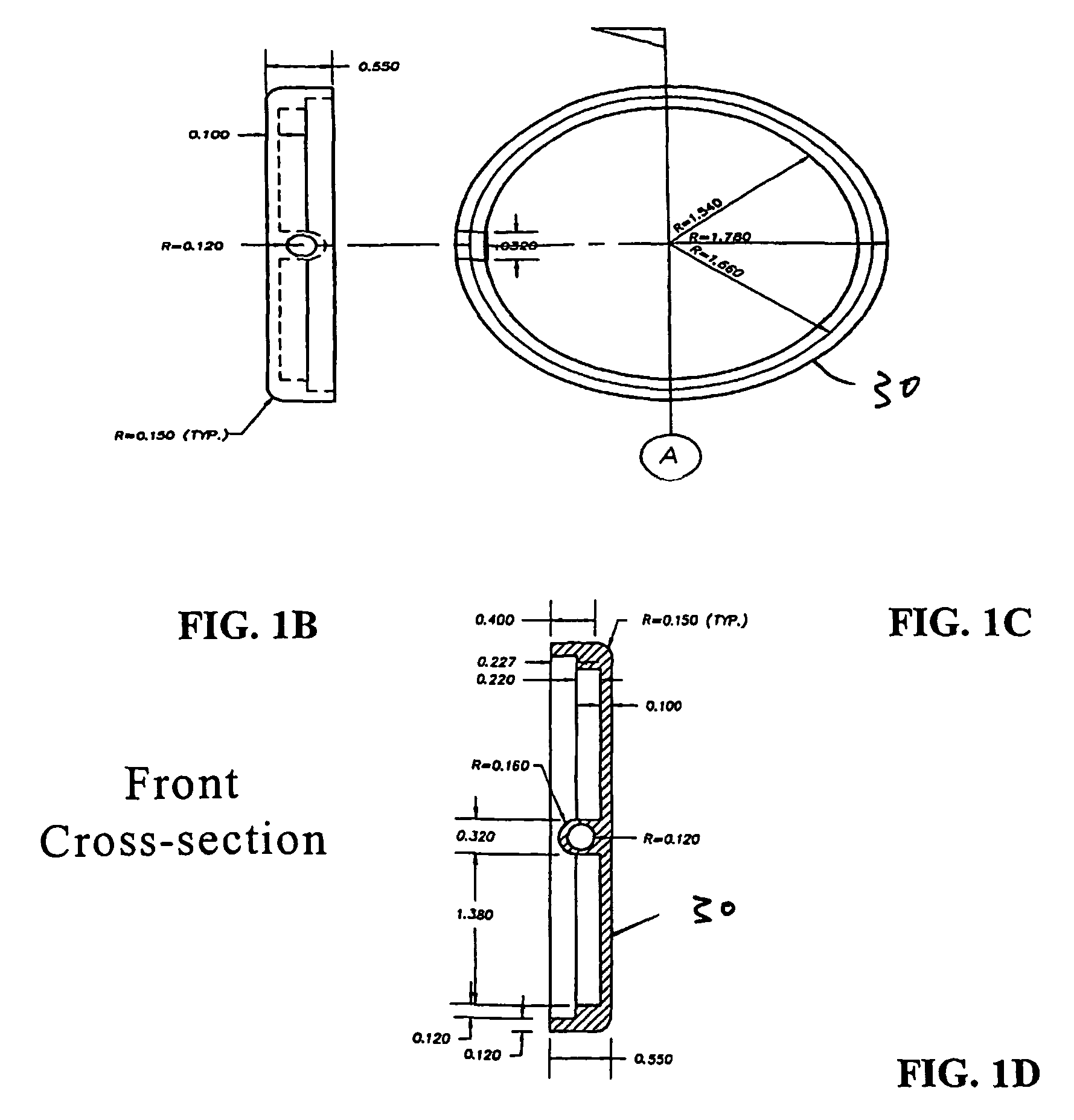
[0069]Reservoir 108 fits inside housing 100 and is connected, e.g., by a pressure fit, to pump mount 110. Pump 50 fits securely in pump mount 110, and is inserted into reservoir 108. Reservoir neck 109 is press fit or threaded into opening 111 in pump mount 110, thereby sealing pump 50 inside reservoir 108.

[0070]FIG. 16 shows a top view of this device. FIG. 17 is a side cross-sectional view of the device along section line A-A in FIG. 16. When pump 50 is moved forwards (to the right in FIG. 17), nozzle 52 is pressed into the pump, thereby drawing liquid from reservoir 108 ...

first embodiment

[0072]When dispensing button 106 is pushed downward, the two angled faces 122 are pressed against the two wedges 112 on either side of pump mount 110. This pressure, in turn, forces the wedges, and thus the pump mount, pump, and reservoir, to move horizontally (laterally) forwards (right in FIG. 18B). This causes nozzle 52 of pump 50 to be pressed into the pump causing it to expel liquid drawn from reservoir 108. In other respects, this device is similar to the first embodiment described herein.

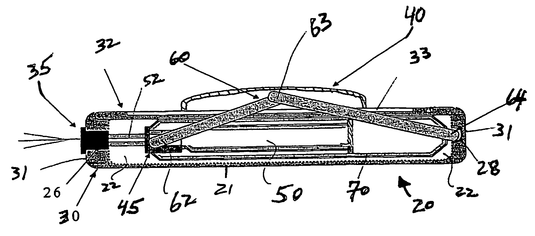
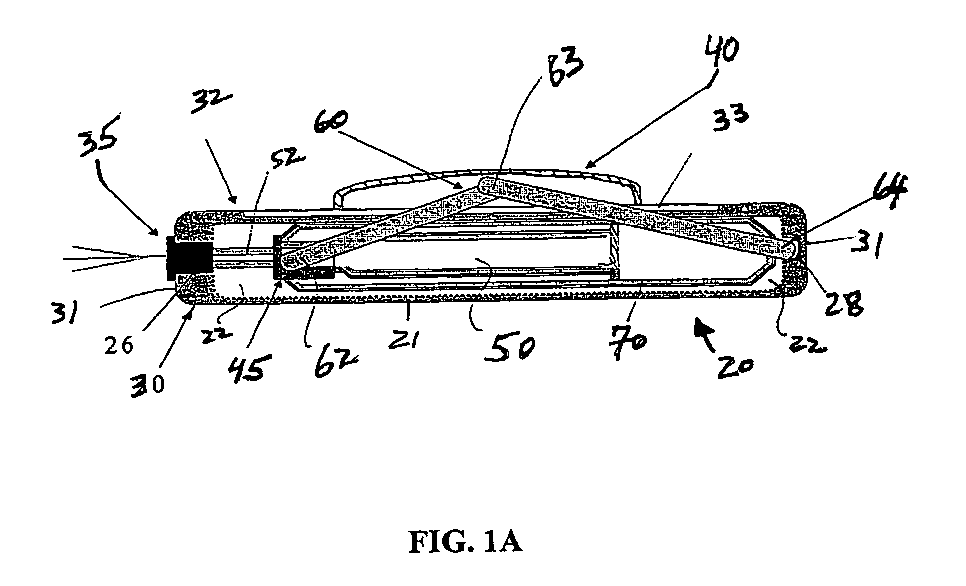
[0073]Thus, in all embodiments, a force in a first direction (e.g., downwards) is applied to a surface of the device, or a dispensing button, which contacts an actuator mechanism that translates the force into a second direction (e.g., horizontally or laterally), which is approximately (or exactly) at 90° to the first direction. The force in the second direction moves an internal pump towards a wall of the device, causing a nozzle of the pump to be pushed into the pump to dispense liquid cont...


PUM


Abstract

A disposable dispensing device for storing and dispensing fluids, such as liquids and gels is disclosed. The dispensing device is a scalable packaging solution including an outer protective housing or shell, optionally a fluid reservoir, and an orifice from which the materials are expelled. The dispensing device can also include a dispensing button that activates an internal pumping system via an actuator mechanism that translates a force in a first direction into a force in a second direction. The dispensing device is particularly useful for liquids such as fragrances or colognes, gels, purified water, dry powders, creams, and pharmaceutical products such as eye ear drops or sprays. The device by design has many uses, is highly portable, and can include an outer reusable and decorative case.

Description

CROSS-REFERENCE TO RELATED APPLICATION[0001]This application claims priority under 35 U.S.C. §371 to international application number PCT / US2004 / 032677, filed on Oct. 4, 2004, which in turn claims priority to U.S. Provisional application No. 60 / 508,533, filed on Oct. 2, 2003. The subject matters of these applications are incorporated herein by reference in their entireties.[0002]This applications claims the benefit of priority of U.S. Provisional Patent Application No. 60 / 508,533, filed on Oct. 2, 2003, the contents of which is incorporated herein by reference in its entirety.TECHNICAL FIELD[0003]This invention relates to self-contained, portable dispensing systems that can store and dispense fluids such as fragrances, colognes, gels, and creams.BACKGROUND OF THE INVENTION[0004]Many consumer products, such as those used for personal care and hygiene, come in the form of liquids, creams, or gels that are sprayed or otherwise applied to the skin, eyes, or mouth. Such products are typi...

Claims


Application Information

Patent Timeline
Patent Type & Authority Patents(United States)
IPC IPC(8): B67D7/84B05B11/00B67D7/58B67D7/06G01F11/06
CPCB05B11/3056B05B11/3057B05B11/1056B05B11/1057
Inventor GILLIARD, II, RALPH J.
Owner THE X GROUP
Why Eureka
Try Eureka