Image forming apparatus and method with improved capabilities of correcting image magnification error

a technology of image magnification error and image forming apparatus, which is applied in the field of image forming apparatus and methods with improved capabilities of correcting image magnification errors, can solve the problems of deviation of image magnification, undesirable positional shift of beam scanning beam on the surface of the photoreceptor, and undue variation of image magnification between the systems, so as to improve the ability of correcting errors, reduce or eliminate the

Inactive Publication Date: 2010-07-20
RICOH KK
View PDF10 Cites 13 Cited by
  • Summary
  • Abstract
  • Description
  • Claims
  • Application Information

AI Technical Summary

Benefits of technology

[0030]Accordingly, it is an object of this invention to provide a novel image forming apparatus and method with improved capabilities of correcting an error of image magnification having most, if not all, of the advantages and features of similarly employed apparatuses and methods, while reducing or eliminating many of the aforementioned disadvantages.
[0031]It is another object to provide a novel image forming apparatus capable of correcting an error of image magnification without prolonging non-writing periods and unduly affecting print speeds.

Problems solved by technology

With regard to the light beam scanning systems, however, several drawbacks have previously been encountered such as, for example, undue variation of image magnification between the systems, which is caused by the variation or dispersion of characteristics of the system (e.g., lens).
This gives rise to undesirable positional shifts of beam scanning on the surface of the photoreceptor, that is, deviations of image magnification (which is hereinafter also referred to as errors) in the horizontal scanning direction.
As a result, several difficulties are encountered in achieving high image qualities.
Furthermore, in the case of forming multiple-color images by the image forming apparatus incorporating multiple lenses for transmitting plural laser beams, the dispersion may become more pronounced by accumulating a shear in color printing (out-of-register color) caused by the errors of image magnification from respective lenses, whereby image qualities are deteriorated especially in color, in this case.
Since the circuit generally takes time from (a) setting a dividing ratio to (b) reaching a predetermined value of the pixel clock frequency, it is difficult to properly change the frequency within the time period between pages during a continuous printing operation, and the magnification corrections are carried out by increasing the interval between the pages, as illustrated in FIG. 17.
Since this increase in the interval may unduly affect the printing speed, the interval of the magnification correction has to increase, that is, the frequency of the correction decreases.
Furthermore, although test patterns are formed for detecting positional deviation between pages in the method disclosed in the application No. 10-213940, this gives rise to another drawback, such as an increased amount of toner consumption in every pattern formation.
In addition, since the corrections are made step by step with the pages, it takes time to complete the correction.

Method used


Image

  • Image forming apparatus and method with improved capabilities of correcting image magnification error
  • Image forming apparatus and method with improved capabilities of correcting image magnification error
  • Image forming apparatus and method with improved capabilities of correcting image magnification error

Examples


first embodiment

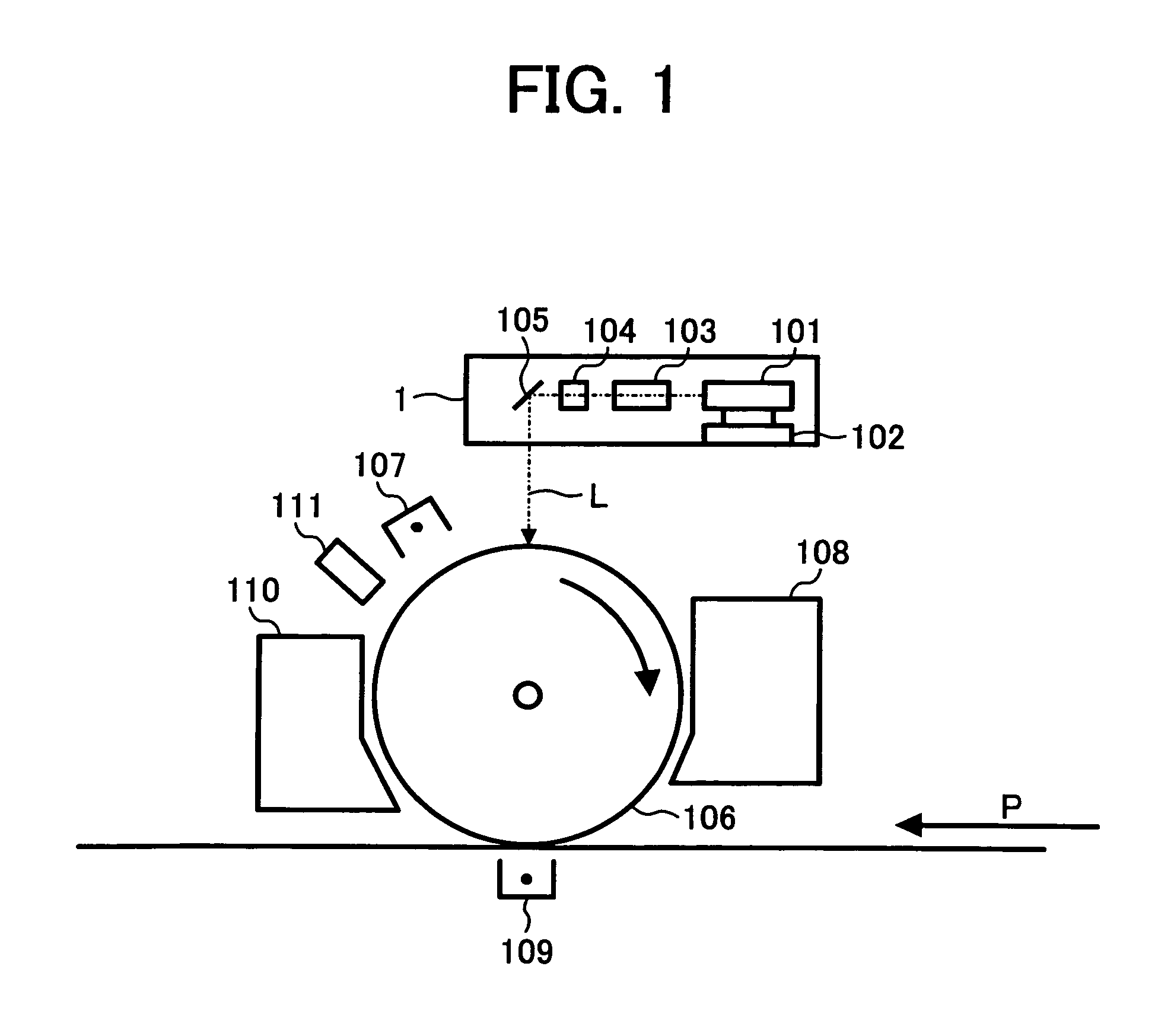
[0118]FIG. 1 is a drawing diagrammatically illustrating major components included in an image forming apparatus according to the invention.

[0119]Referring to FIG. 1, a light beam scanning system (optical unit) 1 comprises a laser diode (which is hereinafter abbreviated as LD) configured to turn on according to image data to be image formed, a collimator lens (not shown) configured to collimate laser beams (or light beams) L emanated from the LD, a cylindrical lens (not shown) configured to form a line focus image of the laser beams parallel to the vertical scanning direction, a polygon mirror 101 configured to deflect the light beams incident from the cylinder lens, a polygon motor 102 configured to rotatory drive the polygon mirror 101 at a high speed, an f-θ lens 103 configured to convert the beam scanning from constant angular velocity to constant linear velocity mode, BTL 104, and a mirror 105.

[0120]BTL (Barrel Toroidal Lens) 104 is configured to focus the light beams in the ver...

second embodiment

[0189]FIG. 11 is a drawing diagrammatically illustrating major components included in a full-color image forming apparatus according to the invention.

[0190]Referring to FIG. 11, the light beam scanning system and image forming control sections included in the full-color image forming apparatus have a similar construction to the image forming apparatus according to the first embodiment, and these unit and sections are configured to perform optical writing operations corresponding to image data, and form electrostatic latent images on a photoreceptor drum 106 serving as a latent image bearing member.

[0191]The photoreceptor drum 106 is adapted to rotate counterclockwise in the drawing.

[0192]On the periphery of the photoreceptor drum 106, there are provided a photoreceptor cleaning unit 110, a dis-electrification unit 111, a charging unit 107, a developer unit (including a Y developer unit, M developer unit, C developer unit, and BK developer unit) 108, and an intermediate transfer belt...

third embodiment

[0213]FIG. 12 is a schematic perspective view illustrating a construction of an image forming apparatus employing a four-drum system of a third embodiment according to the present invention.

[0214]To form a full-color image by superposing monochrome images of four colors, yellow (Y), magenta (M), cyan (C), and black (BK), the image forming apparatus of the present embodiment is provided with four image forming units (each including photoreceptor 106, developer unit 108, charging unit 107, transfer unit 109, and a cleaning unit (e.g., 110, not shown in FIG. 12) and four light beam scanning systems (optical units) 1.

[0215]The image forming apparatus, therefore, has the construction of four image forming apparatuses of FIG. 1 arranged in series.

[0216]In the image forming apparatus, an image in a first color is first formed onto a recording sheet P conveyed by a transfer belt B in the direction of the arrow, then second, third, and fourth images in that order are formed and then transfer...


PUM


Abstract

An image forming apparatus and method that detects a light beam deflected by a polygon mirror at least at two separate locations on the line in the horizontal scanning direction, measures the difference in time of passage between these locations, makes a comparison between the thus determined interval and a reference interval, and generates a proper amount of correction corresponding to the determined interval, such as either correction data adapted to change the frequency of a pixel clock, or further correction data to change the period of the pixel clock by pixels.

Description

[0001]This application claims priority to Japanese Patent Application No. 2005-16147, filed with the Japanese Patent Office on Jan. 24, 2005, the entire contents of which are hereby incorporated by reference.BACKGROUND OF THE INVENTION[0002]1. Field of the Invention[0003]The present invention generally relates to image forming apparatuses and methods, and more specifically to an image forming apparatus and method with improved capabilities of correcting image magnification error without prolonging non-writing periods and unduly affecting print speeds.[0004]2. Discussion of the Background[0005]In increasingly versatile image forming apparatuses, various improvements have been made in the area of image qualities to cope with severe requirements.[0006]In an image forming apparatus such as a copying machine, a copier, a facsimile, and a printer inclusive of their color models, light beam scanning systems are utilized for optical data writing.[0007]The electrophotographic image forming p...

Claims


Application Information

Patent Timeline
Patent Type & Authority Patents(United States)
IPC IPC(8): B41J2/47B41J2/435
CPCB41J2/473G02B26/127G03G15/0415G03G2215/0446
Inventor MAEDA, KATSUHIKO
Owner RICOH KK
Why Eureka
Try Eureka