Floor panel and floor covering composed of such floor panels

a technology of floor panels and floor coverings, applied in the field of floor panels, can solve the problems of unsatisfactory sound, more particularly creaking noise, and require an additional production cost of floor panels, and achieve the effects of reducing the risk of creaking noise, reducing the risk of said undesired noise, and counteracting the risk of creaking nois

Active Publication Date: 2010-07-27
FLOORING IND LTD
View PDF28 Cites 64 Cited by
  • Summary
  • Abstract
  • Description
  • Claims
  • Application Information

AI Technical Summary

Benefits of technology

[0008]According to a first aspect, the present invention thus aims at an improvement having as an aim to counteract the risk of the occurrence of creaking noises. Hereby, it is aspired to reduce this risk by a suitable design of the profiles of the coupling parts, such that the risk of said undesired noises is reduced even if no sliding agent is applied, which, however, does not exclude that a sliding agent still can be applied on the coupling parts of the floor panels according to the invention.
[0010]According to a preferred characteristic, the support portions comprise abutment portions preventing a relative mutual shifting between the contact surfaces of the contact portions and thereby effecting the aforementioned fixation.
[0011]In the most preferred form of embodiment, the floor panels are characterized in that, in the coupled condition, a tension force causes a reaction compression force between the cooperating contact surfaces of the contact portions, as well as between the contact surfaces of the cooperating support surfaces of the support portions, such that at all the contact surfaces, a so-called “pretension” is present. This has the advantage that, when the contact portion that is situated at the underside of the aforementioned tongue, moves somewhat up and down, the contact portion situated at the aforementioned lower lip necessarily follows in this movement when the panels are coupled.

Problems solved by technology

With the floor panels of the above-mentioned type, it was found that, when walking upon a floor covering that is composed of such floor panels, occasionally it may occur that an undesired sound, more particularly a creaking noise, is produced.
Also, in the coupling parts themselves certain deformations may occur as a result of a varying external load, thus also when the floor covering is being walked upon.
This technique has as a disadvantage that it requires an additional production cost of the floor panels, although this cost is very small.
On the other hand, it has also been found that, notwithstanding the use of such sliding agent, it sometimes still occurs that, when such floor covering is being walked upon, still too many undesired sounds, caused by minor movements among the mutually coupled coupling parts, will occur.

Method used


Image

  • Floor panel and floor covering composed of such floor panels
  • Floor panel and floor covering composed of such floor panels
  • Floor panel and floor covering composed of such floor panels

Examples


Embodiment Construction

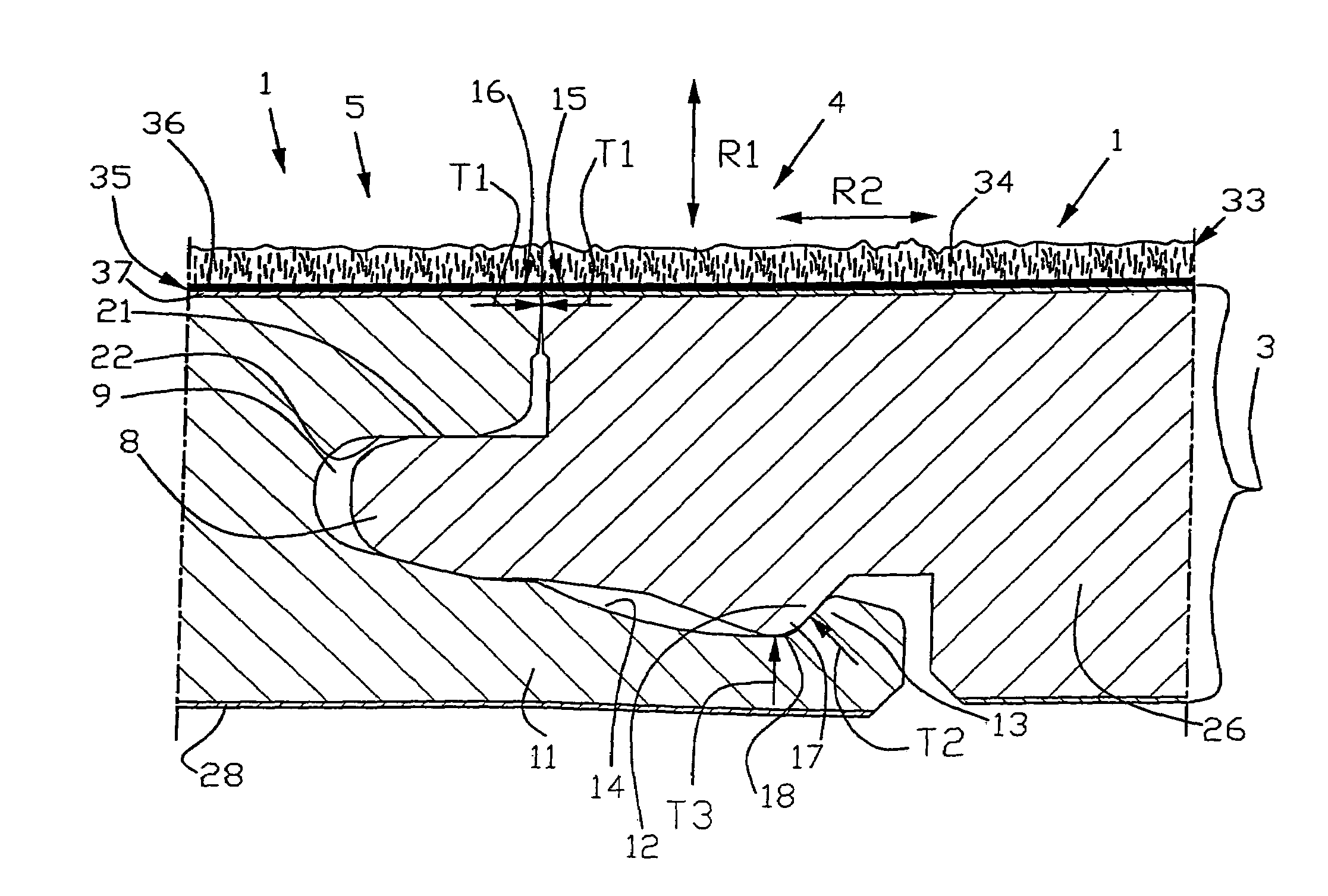
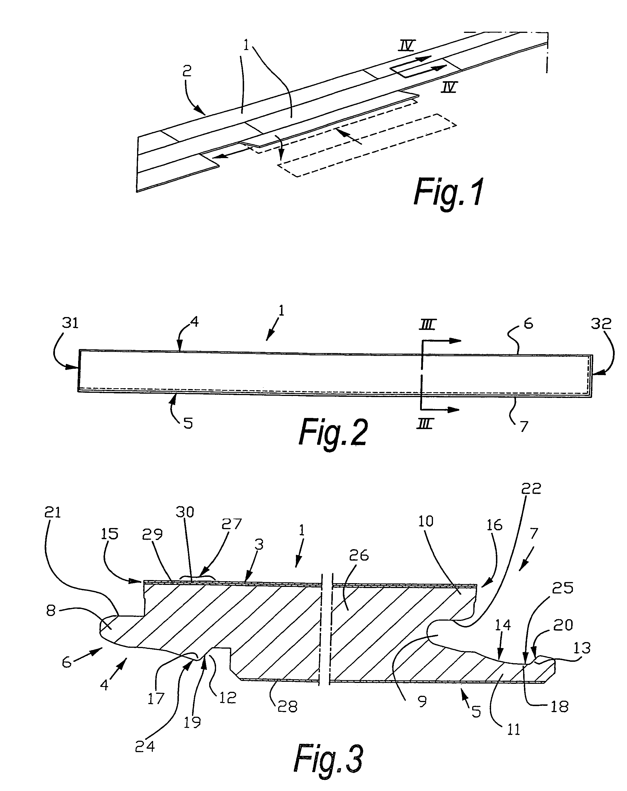
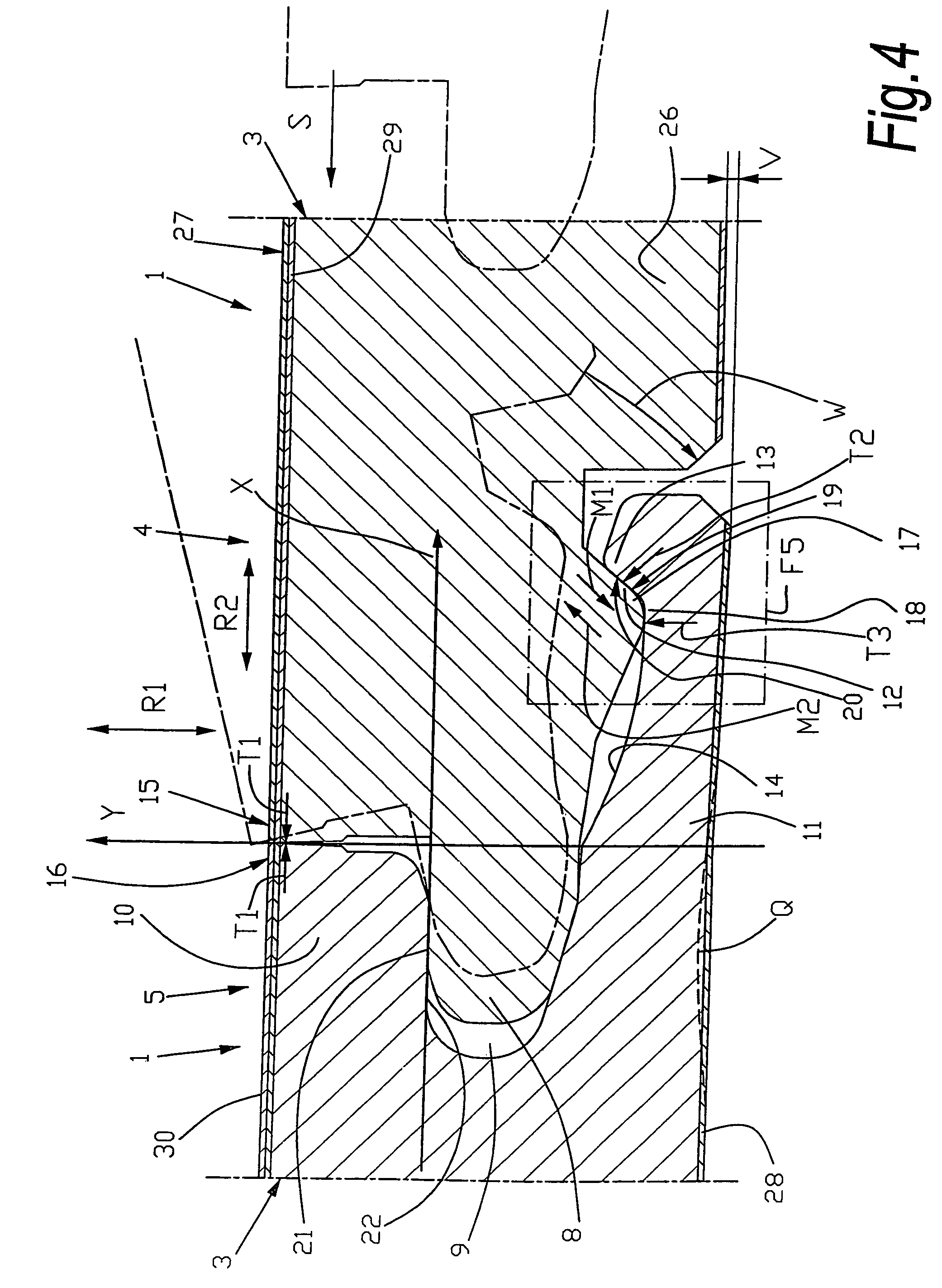
[0029]As represented in FIG. 1, the invention relates to floor panels 1, more particularly hard floor panels, which can be connected to each other in order to form a floor covering 2.

[0030]According to the first aspect of the present invention, such floor panel 1 consists of a board-shaped element 3 and this floor panel 1, as represented in FIGS. 2 and 3, at least at two opposite edges 4-5, is provided with coupling parts 6-7 that enable several of such floor panels 1 to be coupled to each other, whereby these coupling parts 6-7, as illustrated in FIG. 4, in coupled condition provide a locking in a first direction R1 perpendicular to the plane of the floor panels 1, as well as in a second direction R2 perpendicular to the respective edges 4-5 and parallel to the plane of the floor panels 1, and further whereby said coupling parts 6-7 comprise a tongue 8 and a groove 9, the groove 9 being located between an upper lip 10 and a lower lip 11, with the lower lip 11 extending distally bey...


PUM


Abstract

Floor panel in a board shape having at least at two opposite edges coupling parts enabling several of the panels to be coupled to each other, wherein the coupling parts have contact portions forcing the floor panels in the coupled condition with a tension force at least laterally towards each other. The coupling parts also include support portions, which, in the coupled condition of floor panels, create a fixation in the mutual position of the contact portions cooperating under tension.

Description

BACKGROUND OF THE INVENTION[0001]A. Field[0002]This invention relates to a floor panel, as well as to a floor covering composed of such floor panels.[0003]B. Related Technology[0004]More particularly, the invention relates to floor panels, which, at least at two opposite edges, are provided with coupling parts allowing that the floor panels can be coupled to each other mechanically. Examples of such floor panels are described, amongst others, in the patent documents WO 97 / 47834, WO 01 / 98603, U.S. Pat. No. 6,769,219, and WO 2004 / 074597.SUMMARY OF THE INVENTION[0005]More particularly, the invention relates to a floor panel comprising a board-shaped element, whereby this floor panel, at least at two opposite edges, is provided with coupling parts allowing that several of such floor panels can be coupled to each other, whereby these floor panels, in coupled condition of two of such floor panels, provide in a locking in a first direction perpendicular to the plane of the floor panels, as...

Claims


Application Information

Patent Timeline
Patent Type & Authority Patents(United States)
IPC IPC(8): E04B2/00
CPCA47G27/0293E04F15/02E04F15/04Y10T428/167E04F2201/0153E04F2201/023E04F2201/0115E04F15/02038
Inventor CAPPELLE, MARK
Owner FLOORING IND LTD
Why Eureka
Try Eureka