Micromechanical rate-of-rotation sensor

a sensor and micromechanical technology, applied in the direction of acceleration measurement using interia force, turn-sensitive devices, instruments, etc., can solve the problems of reducing the detecting surface of the sensor, achieve high sensitivity for detection of rates, increase the sensitivity of the sensor, and prevent excessive deflection of the vibrating structure about the detection axis

Active Publication Date: 2013-01-15
HANKING ELECTRONICS LTD
View PDF44 Cites 19 Cited by
  • Summary
  • Abstract
  • Description
  • Claims
  • Application Information

AI Technical Summary

Benefits of technology

[0008]The present invention provides, in one aspect, a micromechanical Coriolis rate-of-rotation sensor with a response behavior which can be realized in a manner specific to the axis of rotation and with sufficient sensitivity to rates of rotation in one or more directions, which sensor simultaneously has sufficient robustness with respect to the effect of external shock or vibration in the measuring direction or directions (about a detection axis) in order to meet the requirements of electronic signal processing as far as possible and, in particular, to counteract the risk of the vibrating structure sticking to the substrate.

Problems solved by technology

However, such a measure will, in general, entail a reduction of the moment of inertia of the detection element and thus a decrease of the detecting sensor surface so that the enhanced robustness will be obtained at the cost of lower sensor sensitivity.

Method used


Image

  • Micromechanical rate-of-rotation sensor
  • Micromechanical rate-of-rotation sensor
  • Micromechanical rate-of-rotation sensor

Examples


first embodiment

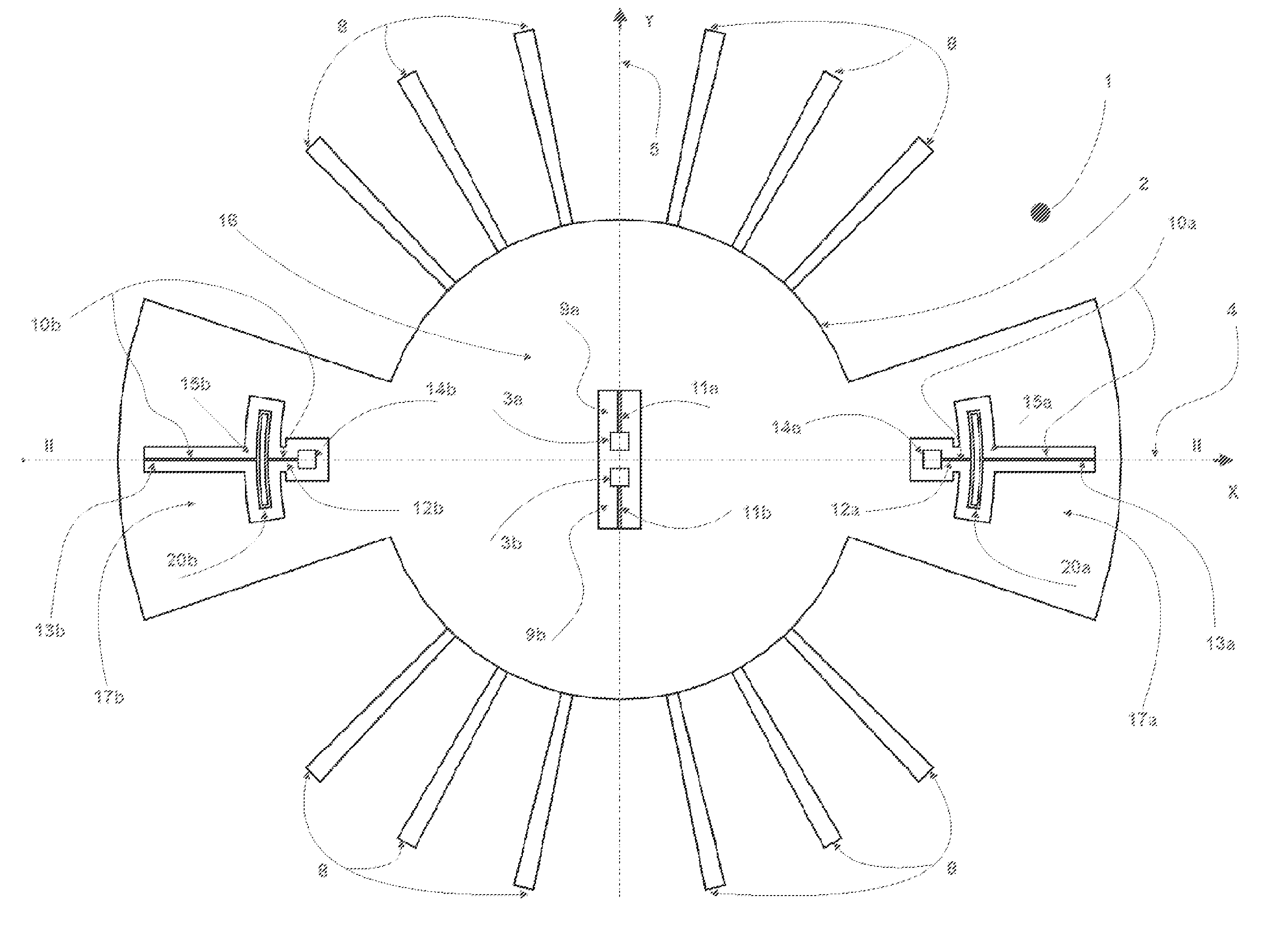
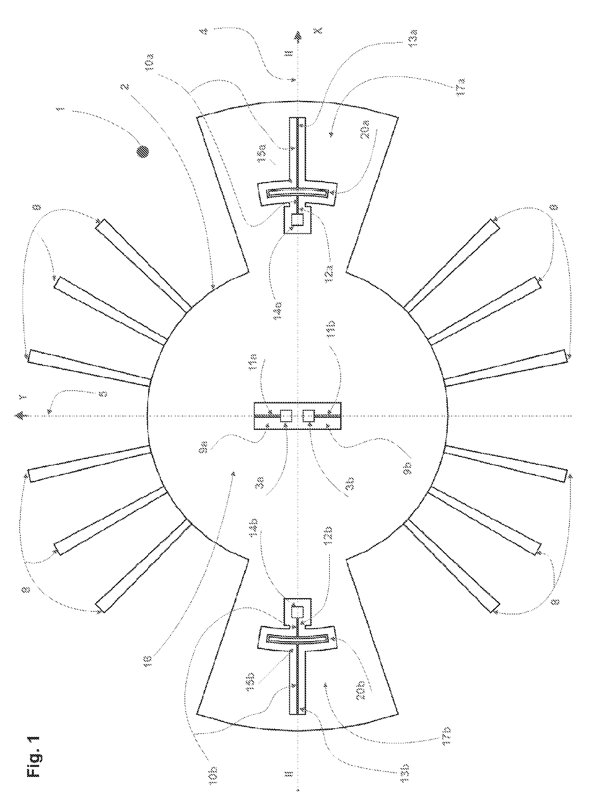
[0036]The sensor illustrated in FIG. 1 in plan view comprises a substrate 1 as a basic element as is sufficiently known from the prior art. A vibrating structure 2 is mounted relative to the substrate 1 at opposite points of suspension arranged in pairs and having the form of mounting pins 3a, 3b, 14a, 14b as the coupling structures. The mounting pins 3a, 3b, together with spring elements 11a, 11b, form first inner suspension means 3a, 3b, 11a, 11b along the Y axis 5, whereas the mounting pins 14a, 14b, together with the spring elements 10a, 10b, form second outer suspension means 14a, 14b, 10a, 10b along the X axis 4. The spring elements 10a, 10b, 11a, 11b connect the vibrating structure 2 to the mounting pins 3a, 3b, 14a, 14b.

[0037]The vibrating structure 2 is mirror-symmetric to both, the detection axis 5 and the sense axis 4. Furthermore, it is point symmetric to the rotation center of the vibrating structure 2, which coincides with the point of origin of the coordinate system...

second embodiment

[0044]FIG. 5 shows the sensor in a schematic plan view, in which the vibrating structure 2 is mounted by means of central suspension means 3, 11a, 11b instead of the first inner suspension means 3a, 3b, 11a, 11b. The central suspension means coincides with the center of gravity of the vibrating structure 2 and is located at the point of origin of the coordinate system.

[0045]As in the first embodiment, the vibrating structure 2 is mirror symmetric to both, the detection axis 5 and the sense axis 4. Furthermore, it is point symmetric to the central suspension means 3, 11a, 11b. As for the rest, the vibrating structure is substantially identical to the vibrating structure 2 of the first embodiment, in which connection it is referred to the description thereof.

[0046]FIG. 6 shows the central suspension means 3, 11a, 11b in an enlarged view. It is comprised of an armature 3 which is firmly connected to the substrate 1 and rises from the substrate 1 in the direction of the drive axis 6. Th...


PUM


Abstract

A micromechanical rate-of-rotation sensor for detecting a rate of rotation about a sense axis includes a substrate, a detection unit, means for generating a rotational oscillation of the detection unit about a drive axis which is orthogonal to the sense axis, and a central suspension means rotatably coupling the detection unit to the substrate in a fulcrum of the detection unit. The central suspension means is configured to permit the detection unit to perform a detection movement about a detection axis orthogonal to the sense axis in the form of a rotational oscillation about the central suspension means. The sensor also includes at least two second suspension means coupling the detection unit and the substrate for providing a response behavior specific to rotation about at least one of the drive axis and the detection axis.

Description

RELATED APPLICATIONS[0001]This is a national phase application under 35 U.S.C. §371 of co-pending International Application No. PCT / EP2008 / 060086 filed Jul. 31, 2008, which claims priority under 35 U.S.C. §119(a) to German Patent Application No. 10 2007 035 806.9 filed on Jul. 31, 2007, the entire contents of all of which are incorporated herein by reference.BACKGROUND OF THE INVENTION[0002]Micromechanical rate-of-rotation sensors are known from the prior art, wherein it may, in general, be distinguished between decoupled and coupled sensors. In decoupled sensors, the vibrating structure comprises a drive means and a detection element which is mechanically separate therefrom. The drive means is brought into a usually stationary state of movement, i.e. the drive oscillation. Spreading of the drive oscillation to the detection element is prevented by a suitable arrangement of spring elements coupling the drive element to the detection element. If a rate of rotation acts upon the senso...

Claims


Application Information

Patent Timeline
Patent Type & Authority Patents(United States)
IPC IPC(8): G01P15/00G01C19/56
CPCG01C19/5712
Inventor HAMMER, HANNO
Owner HANKING ELECTRONICS LTD
Why Eureka
Try Eureka