Microphone optimized for implant use

a microphone and implant technology, applied in the direction of electrical apparatus casings/cabinets/drawers, therapy, physical therapy, etc., can solve the problems of reducing absolute acoustic sensitivity and increasing the noise floor of the input-referred microphone, so as to reduce the ratio of vibration sensitivity to sound sensitivity, increase the sensitivity of the microphone diaphragm, and increase the effect of vibration sensitivity

Inactive Publication Date: 2005-05-12
COCHLEAR LIMITED
View PDF39 Cites 22 Cited by
  • Summary
  • Abstract
  • Description
  • Claims
  • Application Information

AI Technical Summary

Benefits of technology

[0008] A simple dimensional analysis shows that the ratio of vibration sensitivity to sound sensitivity can be reduced by reducing the dimension of the sound receiving element, i.e., the implantable microphone diaphragm. It is generally known that the sensitivity of a microphone diaphragm increases with the area of the diaphragm, e.g., for a circular diaphragm the diameter squared. The vibration sensitivity of the microphone is dominated by the vibrating mass of skin on top of the diaphragm. The effective volume of skin that contributes to the vibration sensitivity may be thought of as dome-shaped as long as the thickness of the layer of skin is above a threshold value. This shape of effective mass can be thought of as similar to the dome shaped mass of effective air over the opening of a Helmholtz cavity. Because the shape of the effective mass remains constant, the vibration sensitivity increases with the volume of the mass and therefore, for a circular diaphragm, increases with the diameter cubed.

Problems solved by technology

On the other hand, absolute acoustic sensitivity is reduced as the area of the diaphragm becomes smaller, and therefore the input-referred noise floor of the microphone increases.

Method used


Image

  • Microphone optimized for implant use
  • Microphone optimized for implant use
  • Microphone optimized for implant use

Examples


first embodiment

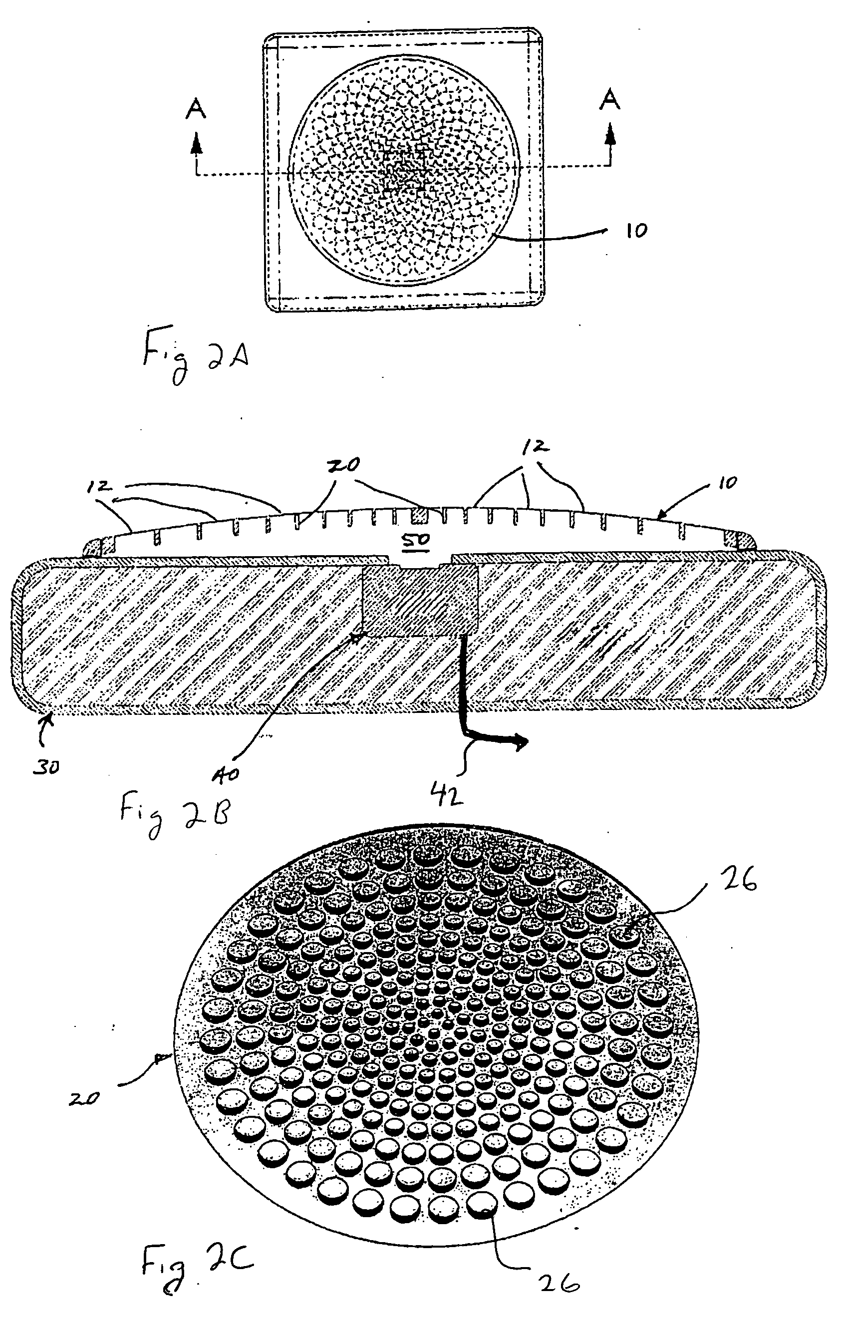
[0040] In a first embodiment, a plurality of individual diaphragm elements are disposed relative to a common chamber that allows for acoustically summing the output of the individual diaphragm elements. In one arrangement of the acoustic summing embodiment shown in FIGS. 2A-2D, a large primary diaphragm 10 of the microphone assembly is subdivided into multiple smaller diaphragm elements 12 by placing a grid-like, rigid or semi-rigid, support structure 20 having a plurality of apertures 26 in contact relation with the diaphragm 10.

[0041] As shown in FIG. 2D, the diaphragm 10, which is formed from a single membrane, may be tensioned over the curved outside surface of the support structure 20.

[0042] Once tensioned over the support structure 20, a retaining ring 22 may clamp the diaphragm 10 and support structure to the housing 30. The diaphragm 10 may be tensioned across each aperture 26 such that the resulting diaphragm elements 12 are operative to vibrate in response to received aco...

second embodiment

[0050] In the present invention, the output signals of a plurality of small diaphragm elements are electronically summed. As shown in FIG. 5 plurality of individual diaphragm elements 90 are juxtaposed relative to a corresponding plurality of microphone transducers 40. The output of each microphone transducer 40 is electronically summed by a summation circuit 60. That is, the summation circuit 60 combines the outputs from the transducers 40. Accordingly, the output signals generated by each of these transducers 40 may be combined to generate a composite output signal, the responsive sum of which will have an adequate acoustic sensitivity for hearing purposes.

[0051] The plurality of individual diaphragm elements 90 and corresponding transducers may be individual units (e.g., separate microphones) or may share one or more structures. For instance, the plurality of diaphragm elements may be formed into an integrated structure as discussed above, or share a common diaphragm.

[0052]FIG. ...


PUM


Abstract

An implantable microphone for use with an implantable hearing instrument that has a reduced vibration sensitivity in comparison with its acoustic sensitivity. The microphone utilizes a plurality of small diaphragms as opposed to a single large diaphragm in order to reduce vibration sensitivity caused by mass loading of the diaphragms by overlying skin and tissue. The acoustic outputs of the plurality of small diaphragms are summed (e.g., acoustically or electronically), which allows the microphone to maintain adequate acoustic sensitivity for hearing augmentation purposes while having a reduced vibration sensitivity. In one aspect, the plurality of diaphragms is formed from a single membrane and a multi-apertured support structure in contact with the membrane. Each aperture in combination with the membrane defines a single diaphragm.

Description

CROSS REFERENCE TO RELATED APPLICATIONS [0001] This application claims priority under 35 U.S.C. 119 to U.S. Provisional Application No. 60 / 518,256 entitled: “MICROPHONE OPTIMIZED FOR IMPLANT USE,” having a filing date of Nov. 7, 2003; the contents of which are incorporated herein as if set forth in full.FIELD OF THE INVENTION [0002] The present invention relates to implanted microphone assemblies, e.g., as employed in hearing aid instruments, and more particularly, to implanted microphone assemblies having reduced sensitivity to undesired sources of vibration. BACKGROUND OF THE INVENTION [0003] In the class of hearing aids generally referred to as implantable hearing instruments, some or all of various hearing augmentation componentry is positioned subcutaneously on, within or proximate to a patient's skull, typically at locations proximate the mastoid process. In this regard, implantable hearing instruments may be generally divided into two sub-classes, namely semi-implantable and ...

Claims


Application Information

Patent Timeline
Patent Type & Authority Applications(United States)
IPC IPC(8): A61FA61N1/36H04R25/00
CPCH04R25/606A61N1/36032A61N1/36038
Inventor MILLER, SCOTT ALLAN IIIWALDMANN, BERND
Owner COCHLEAR LIMITED
Why Eureka
Try Eureka