Current-perpendicular-to-the-plane structure magnetoresistive element and head slider

a technology of magnetoresistive elements and perpendicular to the plane structure, applied in the field of magnetoresistive elements, can solve the problems of deteriorating affecting the establishment of a single domain property in the free ferromagnetic layer, and excessive magnetic field acting in this direction, so as to achieve a higher current level without reducing the sensitivity of the magnetoresistive film

Inactive Publication Date: 2005-07-07
FUJITSU LTD
View PDF5 Cites 20 Cited by
  • Summary
  • Abstract
  • Description
  • Claims
  • Application Information

AI Technical Summary

Benefits of technology

[0007] It is accordingly an object of the present invention to provide a current-perpendicular-to-the-plane structure magnetoresistive element allowing flow of a sensing current having a higher current level without reducing the sensitivity of the magnetoresistive film.
[0009] The CPP structure magnetoresistive element allows the second biasing magnetic field to get opposed to the current field at a position near the rear end of the magnetoresistive film. The second biasing magnetic field overcomes the current field, so that the single domain property is established within the magnetoresistive film in a direction along the medium-opposed surface. On the other hand, the first biasing magnetic field acts in the same direction as the current field at a position near the front end of the magnetoresistive film. The magnetization is allowed to reliably rotate within the magnetoresistive film in response to the inversion of the magnetic flux acting on the magnetoresistive film from a recording medium. The rotation of the magnetization within the magnetoresistive film induces a large variation in the electric resistance of the magnetoresistive film. This causes variation in the voltage level of a sensing current supplied to the magnetoresistive film. This variation in the voltage level is utilized to discriminate binary data. Specifically, the CPP structure magnetoresistive element enables supply of the sensing current having a larger current value to the magnetoresistive film. Moreover, the magnetoresistive film is allowed to maintain a sufficient sensitivity.
[0010] The second regions of the domain controlling films may have a thickness larger than that of the first regions of the domain controlling films. This enables establishment of the second intensity larger than the first intensity based on the second regions.
[0011] The first regions may be made of a material of a first composition having a first residual magnetic flux density, while the second regions may be made of a material of a second composition having a second residual magnetic flux density larger than the first residual magnetic flux density. This likewise enables establishment of the second intensity larger than the first intensity based on the second regions.
[0013] In addition, the rear ends of the domain controlling films may be located at a position backward from the rear end of the magnetoresistive film. This likewise enables establishment of the second intensity larger than the first intensity along the rear end of the magnetoresistive film.
[0015] The CPP structure magnetoresistive element allows the first biasing magnetic field to get opposed to the current field at a position near the front end of the magnetoresistive film. The first biasing magnetic field overcomes the current field, so that the single domain property is established within the magnetoresistive film in a direction along the medium-opposed surface. On the other hand, the second biasing magnetic field acts in the same direction as the current field at a position near the rear end of the magnetoresistive film. The magnetization is allowed to reliably rotate within the magnetoresistive film in response to the inversion of the magnetic flux acting on the magnetoresistive film from a recording medium. The rotation of the magnetization within the magnetoresistive film induces a large variation in the electric resistance of the magnetoresistive film. This causes variation in the voltage level of a sensing current supplied to the magnetoresistive film. This variation in the voltage level is utilized to discriminate binary data. Specifically, the CPP structure magnetoresistive element enables supply of the sensing current having a larger current value to the magnetoresistive film. Moreover, the magnetoresistive film is allowed to maintain a sufficient sensitivity.

Problems solved by technology

This hinders establishment of a single domain property in the free ferromagnetic layer.
The magnetic field excessively acts in this direction in the free ferromagnetic layer.
The sensitivity of the magnetoresistive film may be deteriorated.

Method used


Image

  • Current-perpendicular-to-the-plane structure magnetoresistive element and head slider
  • Current-perpendicular-to-the-plane structure magnetoresistive element and head slider
  • Current-perpendicular-to-the-plane structure magnetoresistive element and head slider

Examples


first embodiment

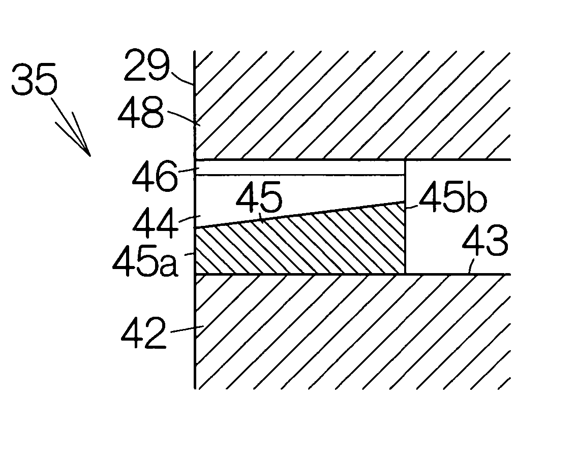
[0064]FIG. 5, schematically illustrates the structure of a CPP structure magnetoresistive (MR) read element 35 according to the present invention. The CPP structure magnetoresistive read element 35 allows establishment of first and second regions 45a, 45b in the domain controlling films 45, respectively. The second region 45b is set thicker than the first region 45a. Here, the thickness of the domain controlling films 45 may gradually increase from the front end to the rear end, for example. Specifically, an inclined surface having an inclination angle to the flattened surface 43 may be defined over the surfaces of the domain controlling films 45.

[0065] As shown in FIG. 6, the first region 45a induces establishment of a first biasing magnetic field 58 having a first intensity of magnetic flux across the magnetoresistive film 44 along the front end of the magnetoresistive film 44. The second region 45b induces establishment of a second biasing magnetic field 59 having a second intens...

second embodiment

[0073]FIG. 11 schematically illustrates the structure of a CPP structure magnetoresistive read element 35a according to the present invention. The CPP structure magnetoresistive read element 35a allows establishment of first and second regions 45a, 45b in the domain controlling films 45. The first region 45a has a first thickness while the second region 45b has a second thickness larger than the first thickness. A step may be defined between the upper surfaces of the first and second regions 45a, 45b. The CPP structure magnetoresistive read element 35a allows establishment of the first biasing magnetic field 58 of the first intensity along the front end of the magnetoresistive film 44. The second biasing magnetic field 59 of the second intensity larger than the first intensity is established near the rear end of the magnetoresistive film 44.

[0074] A magnetic film of a uniform thickness is formed on the flattened surface 43 of the lower electrode 42 in a method of making the CPP stru...

third embodiment

[0077]FIG. 13 schematically illustrates the structure of a CPP structure magnetoresistive read element 35b according to the present invention. The CPP structure magnetoresistive read element 35b include a front film 65 extending rearward from the air bearing surface 29 and a rear film 66 extending rearward from the rear end of the front film 65. The front film 65 is made of a material of a first composition having a first residual magnetic flux density. The front film 65 corresponds to the first region 45a. The rear film 66 is made of a material of a second composition having a second residual magnetic flux density larger than the first residual magnetic flux density. The rear film 66 corresponds to the second region 45b. The material of the first and second composition may be a magnetic material including at least one element from a group consisting of Fe, Ni and Co. Here, the domain controlling films 45 have a uniform thickness. Since the first region 45a is made of the material o...


PUM

PropertyMeasurementUnit
thicknessaaaaaaaaaa
thicknessaaaaaaaaaa
magnetoresistiveaaaaaaaaaa

Abstract

A magnetoresistive film is interposed between domain controlling films in a current-perpendicular-to-the-plane (CPP) structure magnetoresistive element. The domain controlling films designed to establish a first biasing magnetic field of a first intensity across the magnetoresistive film along the front end of the magnetoresistive film and a second biasing magnetic field of a second intensity larger than the first intensity along the rear end of the magnetoresistive film. The second biasing magnetic field serves to establish a single domain property within the magnetoresistive film along the rear end. Although the first biasing magnetic field acts in the same direction as the current field at a position near the front end of the magnetoresistive film, the magnetization is allowed to reliably rotate near the front end. A sensing current having a larger current value can be supplied to the magnetoresistive film. The magnetoresistive film exhibits a sufficient sensitivity.

Description

BACKGROUND OF THE INVENTION [0001] 1. Field of the Invention [0002] The present invention relates to a magnetoresistive element utilizing a magnetoresistive film such as a spin valve film, a tunnel-junction film, or the like. In particular, the invention relates to a current-perpendicular-to-the-plane (CCP) structure magnetoresistive element allowing a sensing current to have a component perpendicular to the surface of a substratum receiving a magnetoresistive film. [0003] 2. Description of the Prior Art [0004] A magnetoresistive film is well known to extend rearward from the front end exposed at the medium-opposed surface or air bearing surface (ABS) by a predetermined length. The magnetoresistive film is interposed between a pair of domain controlling films made of a hard magnetic material. The domain controlling films serve to establish a biasing magnetic field across the magnetoresistive film in a predetermined direction. A single domain property can be realized in the predeterm...

Claims


Application Information

Patent Timeline
Patent Type & Authority Applications(United States)
IPC IPC(8): G01R33/09G11B5/127G11B5/31G11B5/33G11B5/39H01F10/32H01L43/08
CPCB82Y10/00B82Y25/00G01R33/093G11B5/1278G11B5/3116H01L43/08G11B5/3903G11B5/3932G11B2005/3996H01F10/3268G11B5/313H10N50/10
Inventor OSHIMA, HIROTAKA
Owner FUJITSU LTD
Why Eureka
Try Eureka