Quick interface device for delivering ultra-high current

An interface device and current technology, which is applied to the parts, coupling devices, connections, etc. of the connecting device, can solve the problems of troublesome disassembly, poor contact, delayed work process, etc., to achieve convenient installation and maintenance, improve the current level, and work reliably. Effect

Active Publication Date: 2019-09-24
湖南省军民融合装备技术创新中心 +1
View PDF6 Cites 0 Cited by
  • Summary
  • Abstract
  • Description
  • Claims
  • Application Information

AI Technical Summary

Problems solved by technology

[0004] 2. Some mobile electrical equipment in the field sometimes need to repeatedly connect and disconnect super-high current wires. Since super-high current energization has strict requirements on the contact area and contact force of the line connection, the connecting device is usually large in size and complex in structure. Installation is very troublesome, time-consuming and laborious, and even delays the work process, so it is necessary to design a convenient, fast and labor-saving ultra-high current fast interface device
[0005] 3. The ultra-large current transmission brings some new problems to the quick-connect device
First, the temperature rise of the contact surface is easy to be too high, which seriously affects the performance of the product
The second is that the impact force of the super large current can easily make the contact loose, resulting in excessive contact resistance or even poor contact.

Method used


Image

  • Quick interface device for delivering ultra-high current
  • Quick interface device for delivering ultra-high current
  • Quick interface device for delivering ultra-high current

Examples


Embodiment Construction

[0021] The present invention will be described in further detail below in conjunction with the accompanying drawings and embodiments, but these embodiments should not be construed as limiting the present invention.

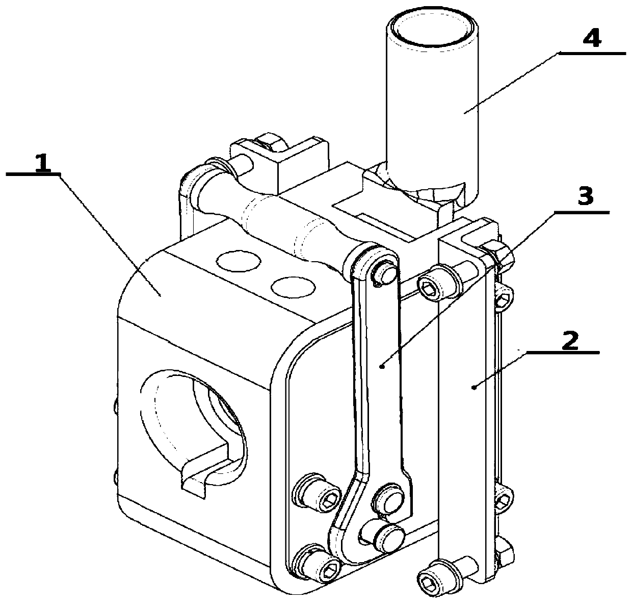
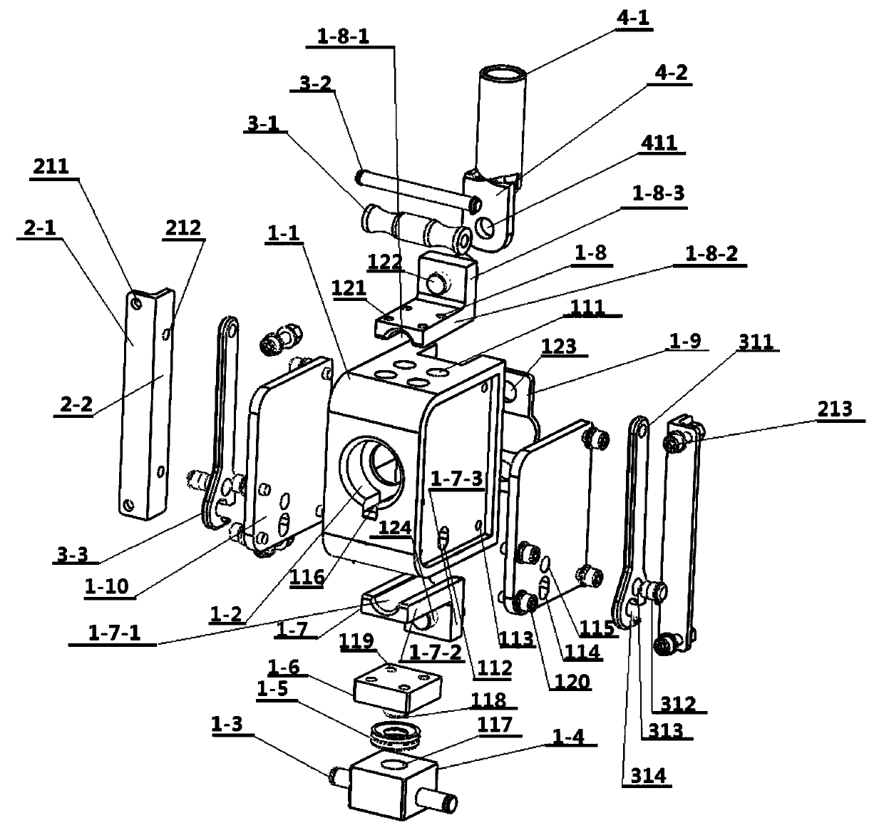
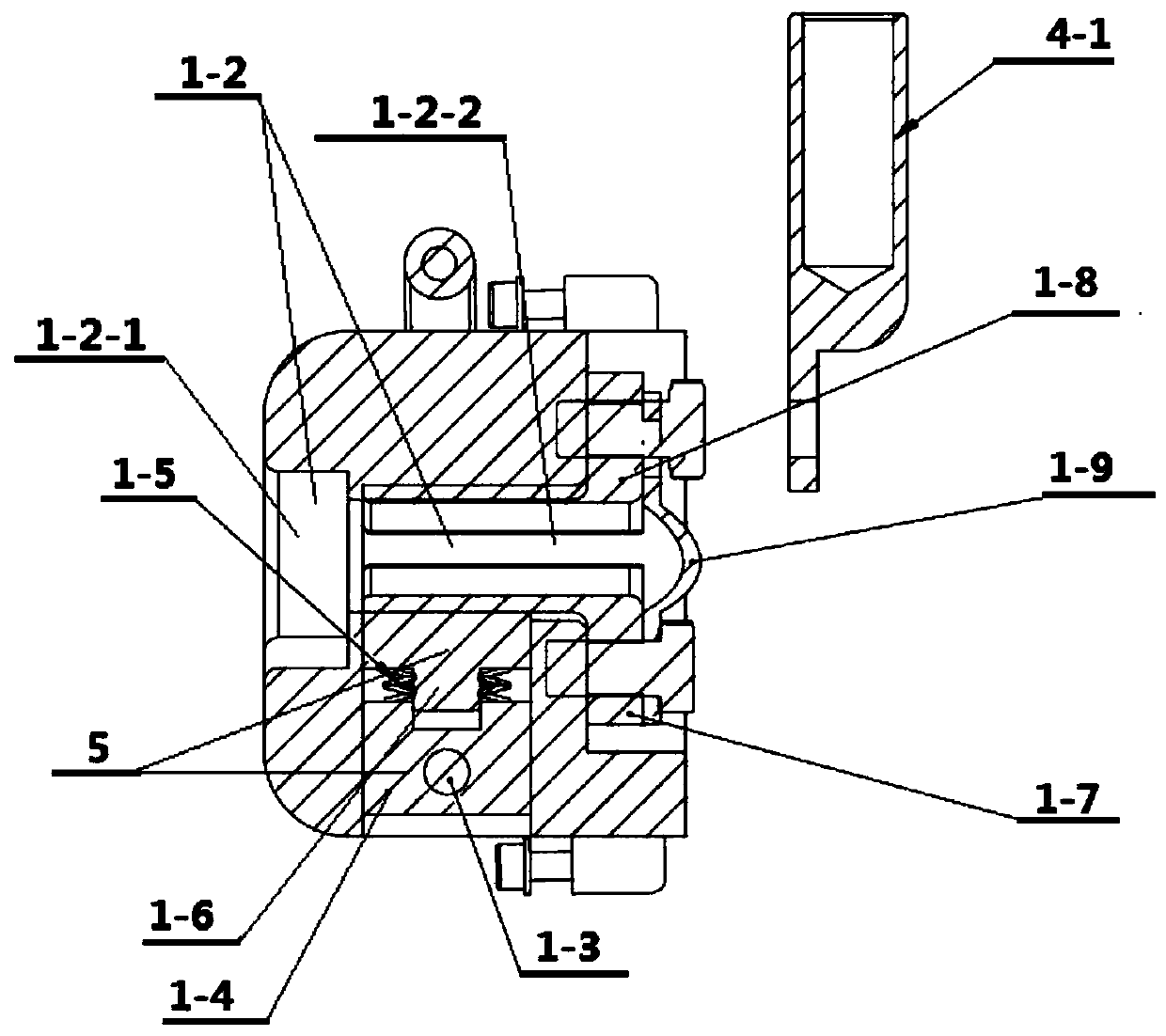
[0022] see Figure 1 to Figure 3 , the fast interface device for transporting super-large current of the present invention includes a seat body 1, the seat body 1 is provided with an insulating shell 1-1, and the side wall of the seat body 1 is provided with a horizontal plug port 1-2, and the horizontal plug port The bottom and top of 1-2 are respectively equipped with a first electrode block 1-7-2 and a third electrode block 1-8-2 connected to an external power supply, and the bottom of the third electrode block 1-8-2 is provided with a plug The first arc-shaped guide groove 1-8-1 matched with the side wall of the terminal, the third electrode block 1-8-2 is provided with four first screw holes 121, and the top of the insulating shell 1-1 is provided with four ...


PUM


Abstract

The invention discloses a rapid interface device for conveying super-heavy current, comprising a seat body whose sidewall is provided with a horizontal plug. The bottom part and the top part of the horizontal plug are respectively provided with a first electrode block and a third electrode block. The bottom part of the third electrode block is provided with a first arc guiding groove. The top partof the first electrode block is provided with a second arc guiding groove. The bottom part of the seat body is provided with a longitudinal cavity communicated with the horizontal plug, and the longitudinal cavity is provided with a movable clamping block and a spring seat. The bottom part of the movable clamping block is provided with an inserting rod. The top part of the spring seat is providedwith an inserting hole matching with the inserting rod. The inserting rod is sleeved by a belleville spring. The top part of the movable clamping block is connected to the first electrode block. Twosides of the spring seat are respectively provided with a connecting shaft extending outside of first waist-type holes at two sides of the seat body. Two sides of the seat body are respectively provided with a hoisting structure connected to the connecting shaft. The invention is advantageous in that plugging is rapid and convenient, connecting is stable; the device can be suitable for hostile working environment in the field; safety and practicality of the device can be improved; the device can be widely applied in the field of electrical connection.

Description

technical field [0001] The invention relates to the field of electrical connectors, in particular to a quick interface device for delivering super large current. Background technique [0002] Quick interface devices are widely used in electronic equipment in various fields such as aviation, ships, weapons, and field power supplies, and can realize fast and reliable electrical connections. With the promotion and application of high-current fast interface devices in recent years, higher requirements have been put forward for the high-current transmission capability, reliability, convenience of plugging and unplugging operations, and environmental adaptability of fast interface devices. The problems existing in the existing high-current quick-connect device are: [0003] 1. The transmission current is limited. Electrical equipment has higher and higher requirements for the working current of the quick-connect device. Some high-power special electrical equipment has a working ...

Claims


Application Information

Patent Timeline
Patent Type & Authority Patents(China)
IPC IPC(8): H01R13/627H01R13/629H01R13/639H01R13/533
Inventor 毛卫聂子玲朱俊杰叶伟伟刘景光韩一刘德志曹健
Owner 湖南省军民融合装备技术创新中心
Why Eureka
Try Eureka