Automatic mine switch

An automatic switch and mine-used technology, which is applied in the direction of electric switches, high-voltage/high-current switches, high-voltage air circuit breakers, etc., can solve unsatisfactory problems, meet the requirements of electricity consumption, and increase the rated working voltage and current level. Effect

Inactive Publication Date: 2013-12-18
JUDA MINING IND
View PDF4 Cites 0 Cited by
  • Summary
  • Abstract
  • Description
  • Claims
  • Application Information

AI Technical Summary

Problems solved by technology

For example, in the DC system, the rated operating voltage of low-voltage electrical appliances can be as high as 1000V. For this, many manufacturers at home and abroad have introduced various circuit breaker wiring application schemes. Where it's good enough, its structure is in dire need of improvement

Method used


Image

  • Automatic mine switch
  • Automatic mine switch
  • Automatic mine switch

Examples


Embodiment 1

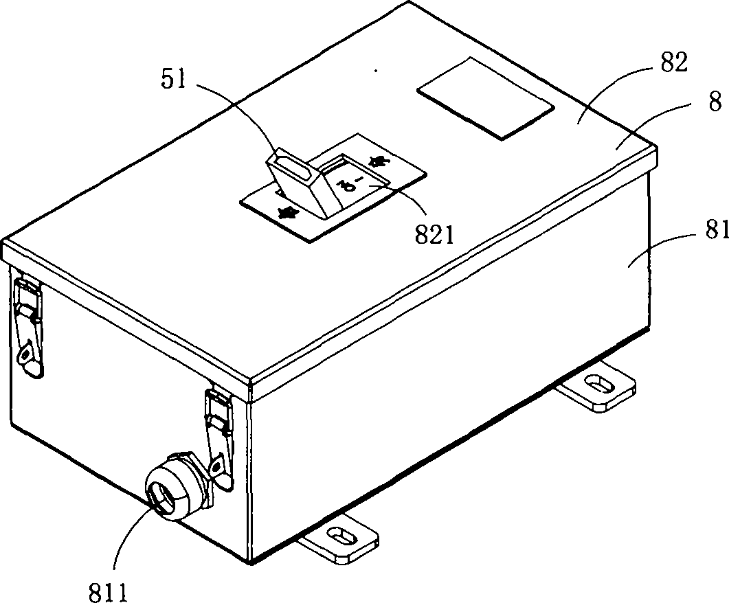
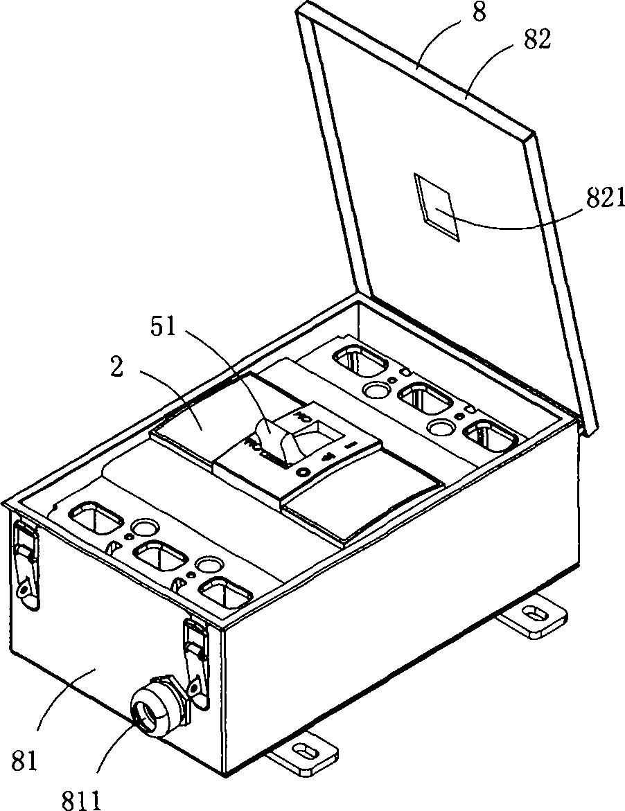
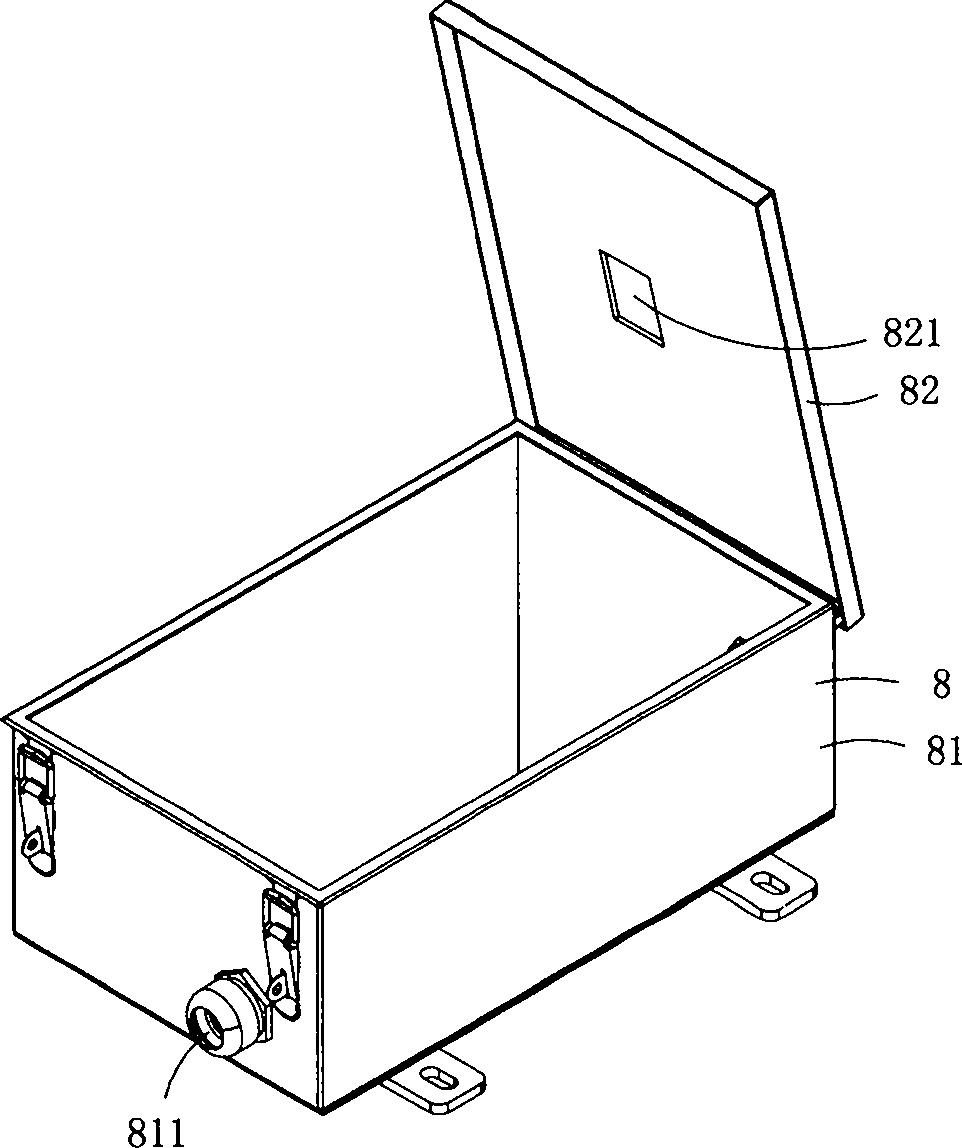
[0016] Figure 1 to Figure 4 A first embodiment of the invention is shown, in which figure 1 It is a schematic diagram of a three-dimensional structure of the first structure of the present invention; figure 2 Yes figure 1 A schematic diagram of a three-dimensional structure when the mine automatic switch is in an open state; image 3 Yes figure 1 A schematic diagram of a three-dimensional structure of the metal box in the mine automatic switch shown; Figure 4 Yes figure 1 A schematic diagram of a three-dimensional structure of the mine automatic switch shown after the metal box is removed.

[0017] This embodiment is an automatic switch, see Figure 1 to Figure 4 As shown, it includes a plastic base 1, a plastic upper cover 2, a wiring assembly 3 arranged on the base 1, a contact system 4, an operating mechanism 5, an arc extinguishing mechanism 6, a tripping device 7 and a metal box body 8; the contact The head system includes three static contacts 41 and three movi...

Embodiment 2

[0023] Figure 5 to Figure 7 A second embodiment of the invention is shown, in which Figure 5 It is a schematic diagram of a three-dimensional structure of the second structure of the present invention; Image 6 Yes Figure 5 A schematic diagram of a working state of the mine automatic switch shown; Figure 7 Yes Figure 5 A schematic diagram of the three-dimensional structure of the auxiliary wrench in the mine automatic switch shown.

[0024] This embodiment is basically the same as the first embodiment, the difference is that the operating mechanism also includes an auxiliary wrench 52, and the auxiliary wrench is provided with a socket hole 521 for being sleeved on the handle; The positioning part 9 of the auxiliary wrench is provided with a socket 91, and the auxiliary wrench is inserted into the socket; when manual opening and closing is required, the auxiliary wrench is connected to the handle, and the opening and closing can be performed in a very labor-saving man...


PUM


Abstract

The invention discloses an automatic mine switch. The automatic mine switch comprises a plastic base, a plastic upper cover, a wiring assembly, a contact system, an operation mechanism, an arc extinction mechanism and a trip device, wherein the wiring assembly, the contact system, the operation mechanism, the arc extinction mechanism and the trip device are arranged on the base. The contact system comprises three fixed contacts and three moving contacts. The operation mechanism drives the three moving contacts to achieve synchronous switch-on-off movements. The arc extinction mechanism comprises three arc extinction covers which are matched with the three moving contacts. The wiring assembly comprises a first wire inlet terminal connected with the first fixed contact, a second wire inlet terminal connected with the second fixed contact, a third wire inlet terminal connected with the third fixed contact, a first wire outlet terminal connected with the first moving contact, a second wire outlet terminal connected with the second moving contact, and a third wire outlet terminal connected with the third moving contact. The first wire outlet terminal is in short circuit connection with the second wire outlet terminal, and the second wire inlet terminal is in short circuit connection with the third wire inlet terminal. Compared with a traditional product, the automatic mine switch greatly improves grades of rated working voltage and current.

Description

technical field [0001] The invention belongs to the technical field of low-voltage electrical appliances, and in particular relates to an automatic mine switch. Background technique [0002] With the development of the times, higher requirements have been put forward for low-voltage electrical components used in mines. For example, in the DC system, the rated operating voltage of low-voltage electrical appliances can be as high as 1000V. For this, many manufacturers at home and abroad have introduced various circuit breaker wiring application schemes. Where it is desirable, its structure is in dire need of improvement. Contents of the invention [0003] The object of the present invention is to provide a mining automatic switch with simplified structure, simple operation and high current on-off. [0004] The technical solution for realizing the purpose of the present invention is: a mining automatic switch, including a plastic base, a plastic upper cover, a wiring assemb...

Claims


Application Information

Patent Timeline
Patent Type & Authority Applications(China)
IPC IPC(8): H01H33/02H01H33/53
Inventor 郑建
Owner JUDA MINING IND
Why Eureka
Try Eureka