Method for Actuating a Valve

A solenoid valve, current technology, applied in the direction of valve operation/release device, valve detail, valve device, etc., can solve the problems of fluid column deceleration, noise increase, etc.

Active Publication Date: 2018-11-23
ROBERT BOSCH GMBH
View PDF21 Cites 0 Cited by
  • Summary
  • Abstract
  • Description
  • Claims
  • Application Information

AI Technical Summary

Problems solved by technology

However, when the valve is closed, this results in a sudden deceleration of the accele

Method used


Image

  • Method for Actuating a Valve
  • Method for Actuating a Valve

Examples


Embodiment Construction

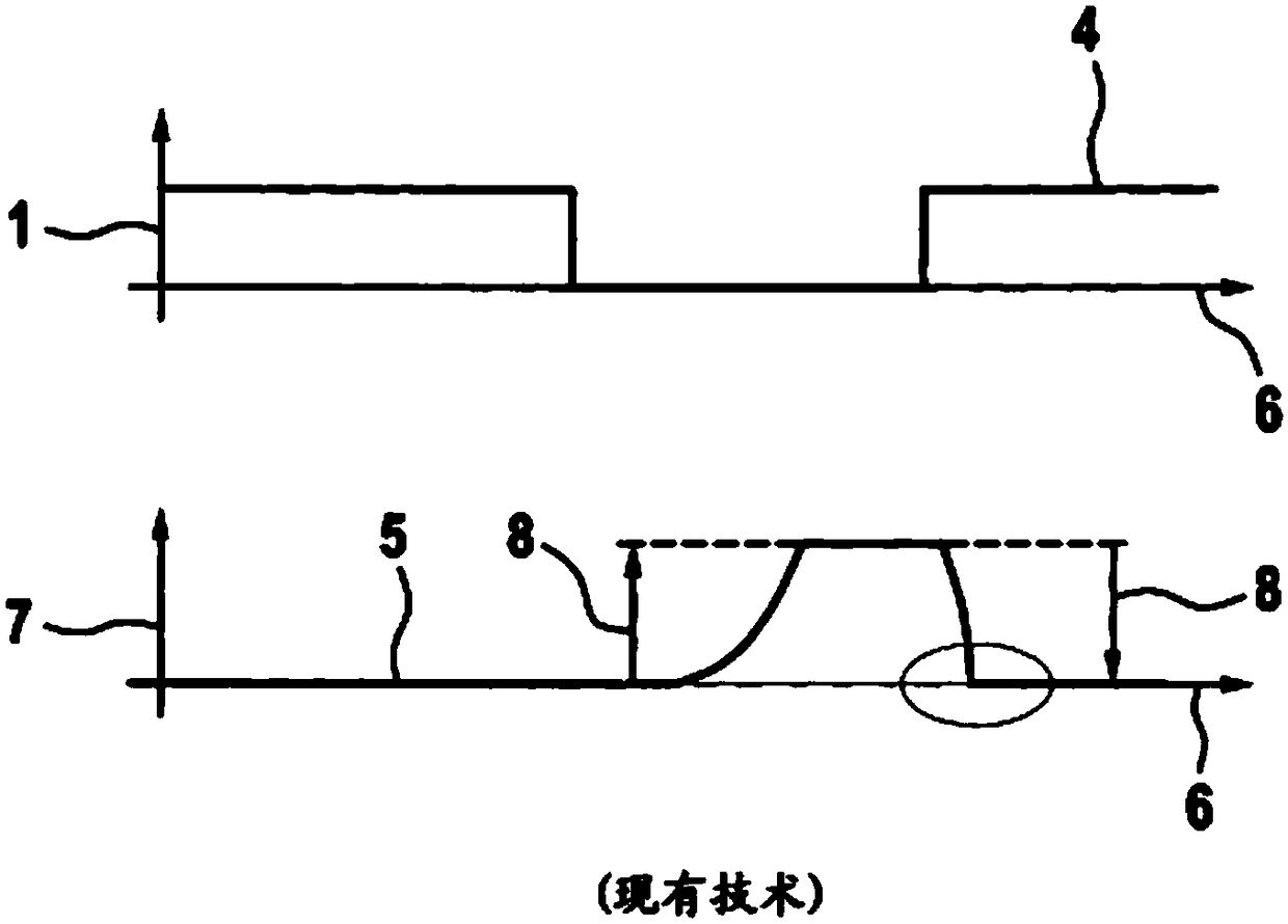
[0032] figure 1 An (idealized) current profile 4 with an associated (idealized) valve position profile 5 according to the prior art is shown schematically. according to figure 1 , the curve of the current 1 over time 6 is plotted in the upper part, and the curve of the valve position 7 over time 6 is plotted in the lower part. From the profile of the valve position 7 it can be seen that the valve is completely closed at the height of the abscissa. for further description figure 1 The current variation curve 4 and the valve position variation curve 5 in , refer to the above-mentioned embodiment for the prior art.

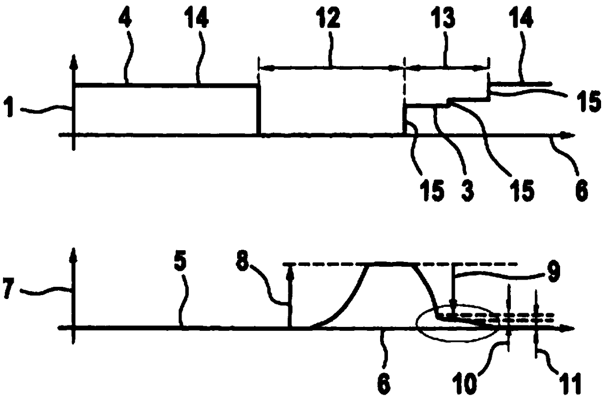
[0033] figure 2 The (idealized) current profile 4 with the associated (idealized) valve position profile 5 produced in the method according to the invention is shown schematically. also according to figure 2 , the curve of the current 1 over time 6 is plotted in the upper part, and the curve of the valve position 7 over time 6 is plotted in the lower part. I...


PUM


Abstract

A method for actuating a valve with a magnetic valve drive, through which electric current(1) is passed to open the valve, to close the valve, and to hold the valve in an open or closed position, includes a)receiving an opening signal. The method further includes b)varying the electric current that is passed through the valve drive as a first current signal(2) to open the valve in response to thereceived opening signal. The method further includes c)receiving a closing signal and varying the electric current that is passed through the valve drive as a second current signal(3) for closing thevalve in response to the received closing signal. The second current signal(3) has at least two variations of the electric current(1) at separate times.

Description

technical field [0001] The invention relates to a method for actuating a valve having a solenoid valve drive through which an electric current is conducted in order to open, close and hold the valve in an open position or a closed position. The invention can be used in particular for the current actuation of feed valves of, for example, ABS systems, TCS systems, ESP systems and / or IPB systems. Here, the abbreviation ABS stands for Anti-lock Brake System, TCS for Traction Control System, ESP for Electronic Stability Program, and IPB for Integrated Power Brake. Background technique [0002] The inlet valves of ABS systems or ESP systems are usually operated in a so-called switching mode or in a so-called (differential pressure) regulating mode. Here, the switching mode is characterized by a short full stroke and the (differential pressure) regulation mode is characterized by a volume flow-dependent partial stroke. [0003] In switching mode, the inlet valve is fully open and...

Claims


Application Information

Patent Timeline
IPC IPC(8): F02D41/20
CPCF02D41/20F02D2041/2058B60T8/36B60T13/662H01F7/18H01F2007/1888H01F2007/1894F16K31/0675B60T13/68
Inventor M·希尔登
Owner ROBERT BOSCH GMBH
Why Eureka
Try Eureka