Intelligent safety valve and use method

A safety valve, intelligent technology, applied in the direction of safety valve, function valve type, balance valve, etc., can solve the problems of piston head and passage wear, safety factor deterioration, wear and other problems, achieve the effect of reducing closing noise and improving service life

Inactive Publication Date: 2018-11-16
泗阳康发电子有限公司
View PDF8 Cites 0 Cited by
  • Summary
  • Abstract
  • Description
  • Claims
  • Application Information

AI Technical Summary

Problems solved by technology

[0003] The above technical solution uses the rotating impeller to drive the air pump to drive the piston to close the valve. The pneumatic connection and power conversion structure used to connect the impeller and the piston are complicated, and the piston mechanism is easily stuck by the pawl structure embedded in the groove of the piston. The timely closing of the valve cannot be guaranteed, and the valve structure composed of springs, pistons, and pawls is easy to cause the piston to The impact between the head and the channel, when the use time becomes longer, it is easy to cause wear and tear on the piston head and the channel, resulting in poor safety factor
In addition, the reset is realized by the contact between the reset button and the piston. This direct contact is easy to cause wear and seizure, resulting in a decrease in the stability of the safety valve structure.

Method used


Image

  • Intelligent safety valve and use method
  • Intelligent safety valve and use method
  • Intelligent safety valve and use method

Examples


specific Embodiment approach

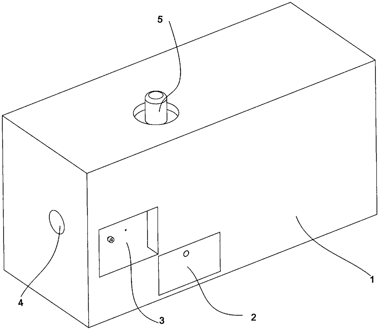
[0019] The specific implementation is as follows, see figure 1 , an intelligent safety valve includes a housing 1, one end of the housing 1 is provided with a water inlet 4, the other end is provided with a water outlet (not shown in the figure), the upper end of the housing 1 is provided with a reset key 5, and the front end of the housing 1 is provided with a slope The gear accommodating chamber, the cam accommodating chamber, the helical gear accommodating chamber and the cam accommodating chamber are respectively provided with a helical gear wall plate and a cam wall plate.

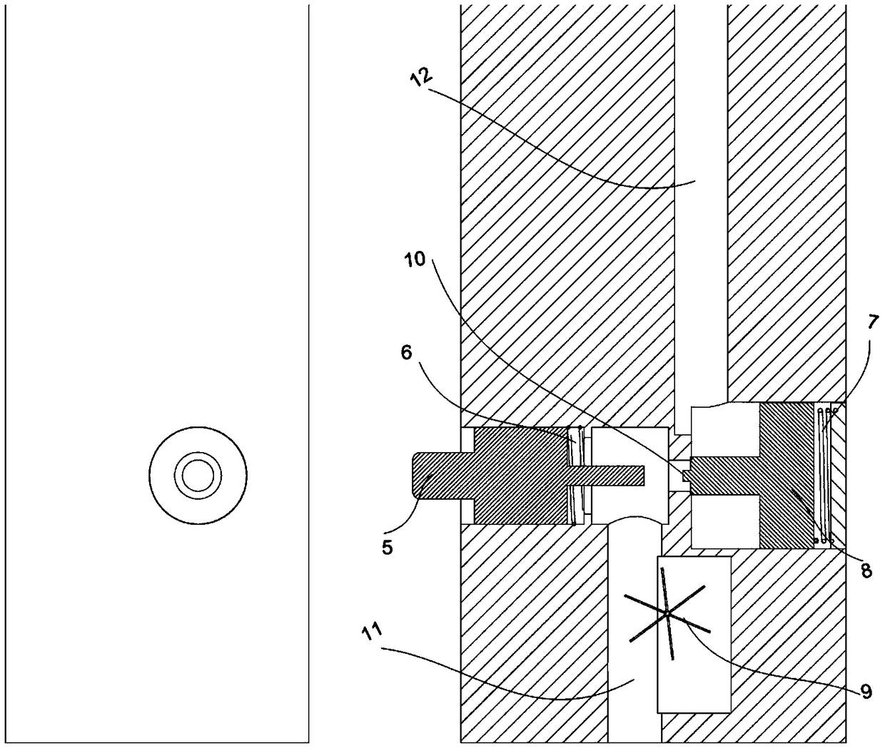
[0020] Further, see figure 2 , the intelligent safety valve includes the internal structure of the shell 1 as follows: the inside of the water inlet 4 is a water inlet channel 11, the water inlet channel is preferably a channel with a circular cross-section, and one side of the water inlet channel 11 is provided with a chamber for accommodating the impeller 9, and the water inlet channel The end of ...


PUM


Abstract

The invention relates to an intelligent safety valve. Traditional safety valves usually adopt traditional driving methods to detect water flow and control valve closing, for example, an American invention US 2012/0153195, the traditional methods are prone to resulting in impact between a piston head and a passage, and wear of the piston head and the passage is prone to occurring and leading to deterioration of a safety factor when the time of use becomes longer. In addition, reset is realized by the contact between a reset button and a piston, but the direct contact method is prone to resulting in wear and seizure and a decrease in the stability of a safety valve structure. In view of the above shortcomings, the intelligent safety valve is provided, the intelligent safety valve comprises ashell and a reset button, wherein a water inlet is formed in one end of the shell, the water inlet communicates with a water inlet channel, a water outlet is formed in the other end of the shell, andthe water outlet communicates with a water outlet channel; the reset button is arranged on one side of the shell and is used for resetting the safety valve; and an impeller is arranged in the water inlet channel and rotates coaxially with a first helical gear arranged outside the water inlet channel.

Description

technical field [0001] The invention relates to a safety valve, especially a safety valve for water flow. Background technique [0002] Traditional safety valves usually use traditional driving methods to detect water flow and control valve closure. For example, the US invention US2012 / 0153195 discloses the following content: in the case of abnormal fluid flow, the automatic shut-off valve cuts off the fluid flow. As fluid flows through the valve, a rotor inside the valve turns. The rotor turns the air pump and causes the air pressure to increase. When the predetermined air pressure is reached, the increased air pressure causes the closing piston to move to the closed position. Shutoff valves also include an adjustable bleed needle to slowly bleed air pressure when fluid flow ceases, resetting the valve. A detent is provided for holding the closing piston in the open position. A pawl spring and compression bolt are provided to adjust the force on the pawl. Close the shu...

Claims


Application Information

Patent Timeline
Patent Type & Authority Applications(China)
IPC IPC(8): F16K17/00F16K37/00
CPCF16K17/00F16K37/0041F16K37/005
Inventor 潘淑微宋荣
Owner 泗阳康发电子有限公司
Why Eureka
Try Eureka