Structure of driver's airbag cushion of vehicle

a technology for airbags and vehicles, which is applied in the direction of vehicle components, pedestrian/occupant safety arrangements, vehicular safety arrangments, etc., can solve the problems of increasing the weight of the vehicle, increasing the cost of the vehicle, and reducing so as to improve the fuel efficiency of the vehicle, reduce the cost of the vehicle, and reduce the weight

Inactive Publication Date: 2010-07-27
HYUNDAI MOTOR CO LTD
View PDF12 Cites 31 Cited by
  • Summary
  • Abstract
  • Description
  • Claims
  • Application Information

AI Technical Summary

Benefits of technology

[0009]Various aspects of the present invention provide for a structure of a driver's airbag cushion of a vehicle that can protect the driver's lower body as well as the driver's upper body and head, without mounting a knee airbag at the lower portion of the crash pad, such that it is possible to reduce the cost of the vehicle, improve the fuel efficiency of the vehicle by reducing the weight, and remove inconvenience when a passenger is sitting on the seat or gets in / out of the vehicle.
[0011]The pelvis chamber may be configured to receive inflation gas. The temporary blocking member may include a tearing portion formed at a predetermined portion of the blocking member and that capable of being torn along a cutting line by the applied tensile force, and the tensile force-providing member may include a link tether having an end sewn to the tearing portion of the temporary blocking member and the other end sewn to the inside of the airbag cushion that pertains to the pelvis chamber. The pelvis chamber may be dimensioned and configured to prevent a driver's pelvis and lower body from moving toward front of the vehicle as the pelvis chamber fully expands. The face chamber may be dimensioned and configured to prevent a driver's head and upper body from moving toward front of the vehicle as the face chamber fully expands.
[0017]According to other aspects of the present invention, it is possible to protect the driver's lower body as well as the driver's upper body and head, without mounting a knee airbag at the lower portion of the crash pad. Further, it is possible to reduce the cost of the vehicle, improve the fuel efficiency of the vehicle by reducing the weight, and remove inconvenience when a passenger is sitting on the seat or gets in / out of the vehicle because it is not needed to secure a space for a knee airbag as in the related art.

Problems solved by technology

However, when a knee airbag is mounted in a vehicle as described above, in addition to increasing the cost of the vehicle, the weight of the vehicle is increased by the weight of the knee airbag itself, thereby decreasing the fuel efficiency of the vehicle.
Further, because a space for the knee airbag is needed at the lower portion of the crush pad, a passenger feels inconvenience when sitting on the seat or getting in / out of the vehicle and it takes more time and efforts to mount the knee airbag.

Method used


Image

  • Structure of driver's airbag cushion of vehicle
  • Structure of driver's airbag cushion of vehicle
  • Structure of driver's airbag cushion of vehicle

Examples


Embodiment Construction

[0024]Reference will now be made in detail to various embodiments of the present invention(s), examples of which are illustrated in the accompanying drawings and described below. While the invention(s) will be described in conjunction with exemplary embodiments, it will be understood that present description is not intended to limit the invention(s) to those exemplary embodiments. On the contrary, the invention(s) is / are intended to cover not only the exemplary embodiments, but also various alternatives, modifications, equivalents and other embodiments, which may be included within the spirit and scope of the invention as defined by the appended claims.

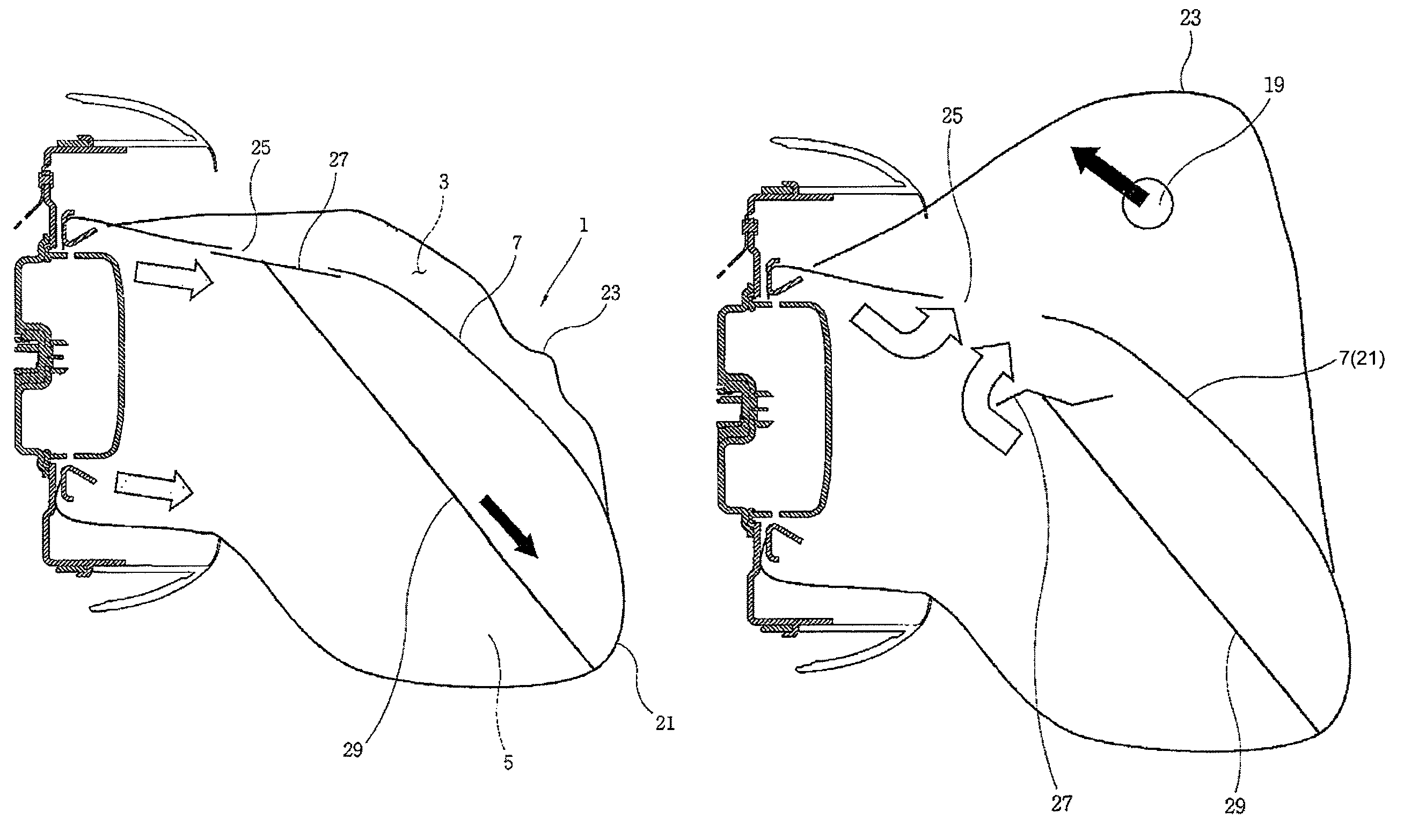
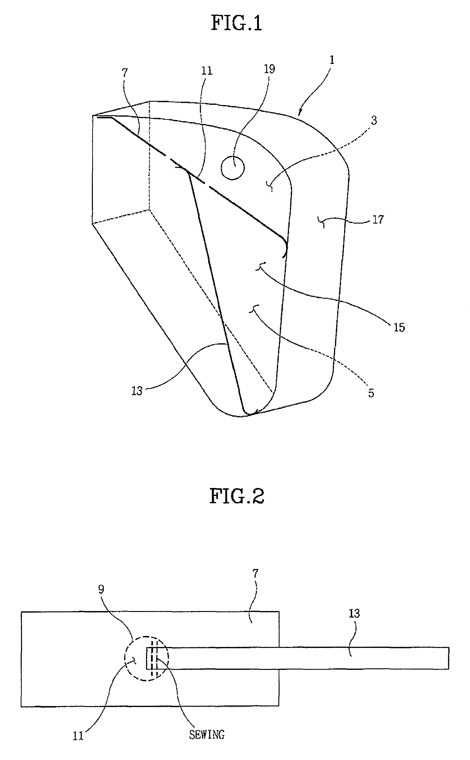
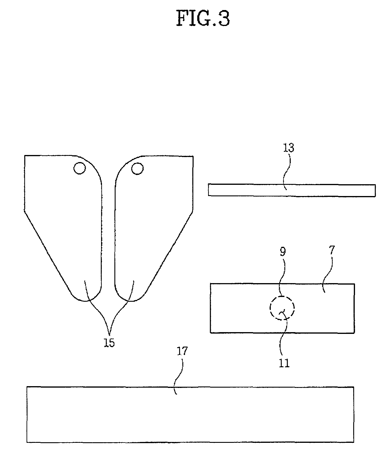
[0025]Referring to FIGS. 1 and 4, an structure for a driver's airbag cushion of a vehicle according to embodiments of the invention includes: a blocking member 7 that extends from the rear upper end of an airbag cushion 1 to the front in the airbag cushion 1, assuming that the front direction is a direction in which airbag cushion 1 e...


PUM


Abstract

A structure for a driver's airbag cushion of a vehicle is provided to protect the driver's lower body as well as the driver's upper body and head, without mounting a knee airbag at the lower portion of the crash pad. The structure may include a blocking member that extends from a rear upper end of an airbag cushion to a front end of the airbag cushion and divides the interior of the airbag cushion into a face chamber defined by a front upper space of the airbag cushion and a pelvis chamber defined by a lower space thereof, the blocking member blocks the face and pelvis chambers, a temporary blocking member provided at a predetermined portion of the blocking member to control fluid-communication between the face chamber and the pelvis chamber when a tensile force is applied thereto, and / or a tensile force-providing member that applies tensile force to the temporary blocking member so that the pelvis chamber may be communicated with the face chamber by releasing the temporary blocking member when the pelvis chamber substantially expands.

Description

CROSS-REFERENCE TO RELATED APPLICATION[0001]The present application is based on, and claims priority to Korean Patent Application Number 10-2007-0130876, filed on Dec. 14, 2007, the entire contents of which is hereby incorporated herein for all purposes by this reference herein.BACKGROUND OF THE INVENTION[0002]1. Field of the Invention[0003]The present invention relates to an structure for a driver's airbag cushion of a vehicle, particularly a technology that can protect all of the upper body and the lower body of a driver by providing a function that holds the driver's pelvis using simple structure and configuration.[0004]2. Description of Related Art[0005]The driver's airbag is mounted at the center of the steering wheel in the related art so that an airbag cushion protects mainly the driver's upper body and head in an accident.[0006]Further, when a knee airbag is mounted in the crash pad, an airbag cushion of the knee airbag protects the driver's lower body in a car collision, in...

Claims


Application Information

Patent Timeline
Patent Type & Authority Patents(United States)
IPC IPC(8): B60R21/233B60R21/26B60R21/231
CPCB60R21/231B60R2021/23533B60R21/2032B60R21/2338B60R21/239B60R2021/23576
Inventor CHO, YOUNGNAM
Owner HYUNDAI MOTOR CO LTD
Why Eureka
Try Eureka