Connector for a thermal cutting system or welding system

a technology of thermal cutting system and connecting assembly, which is applied in the direction of plasma welding apparatus, coupling device connection, manufacturing tools, etc., can solve the problems of disengagement of locking device, and achieve the effect of easy alignment and connection and limited receiving spa

Active Publication Date: 2010-07-27
HYPERTHERM INC
View PDF19 Cites 12 Cited by
  • Summary
  • Abstract
  • Description
  • Claims
  • Application Information

AI Technical Summary

Problems solved by technology

The locking device can cause, upon application of a force on a contact member or a rotational moment on the contact member, disengagement of the locking device relative to the stationary receiving mechanism.

Method used


Image

  • Connector for a thermal cutting system or welding system
  • Connector for a thermal cutting system or welding system
  • Connector for a thermal cutting system or welding system

Examples


Embodiment Construction

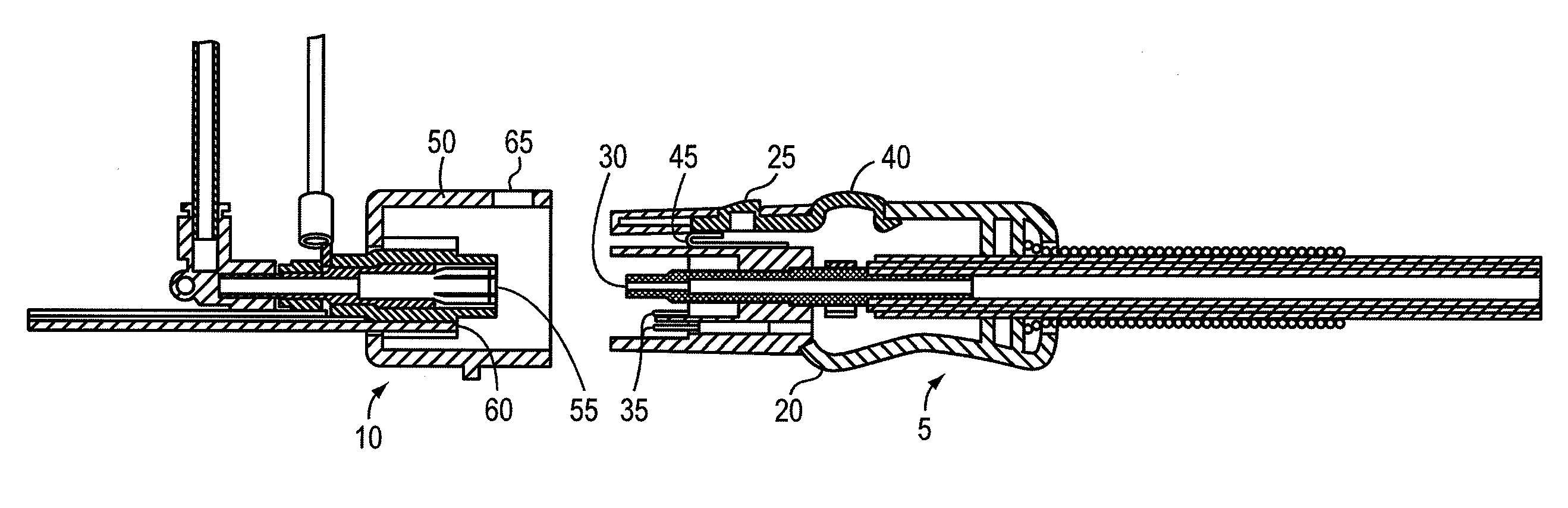
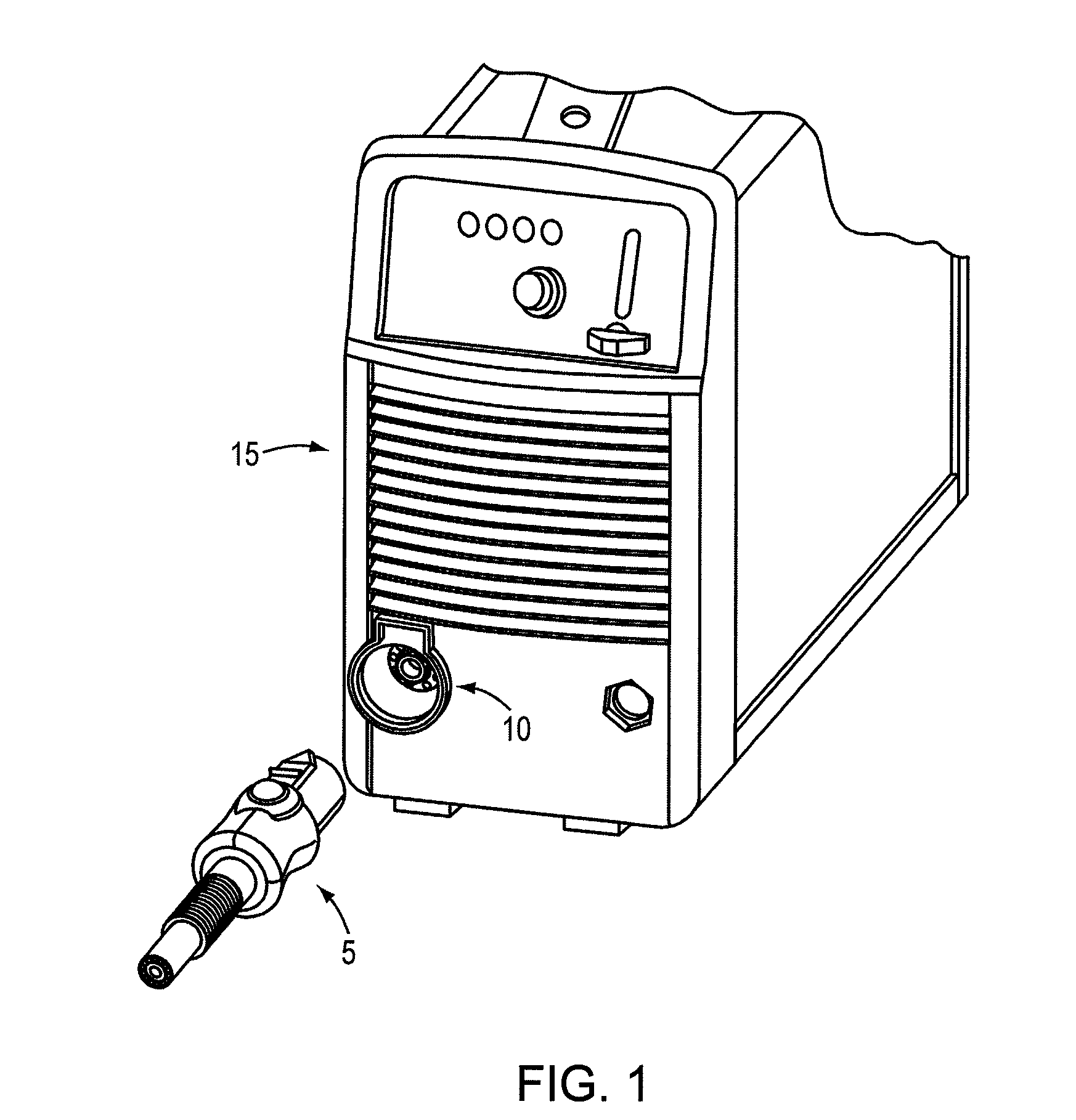
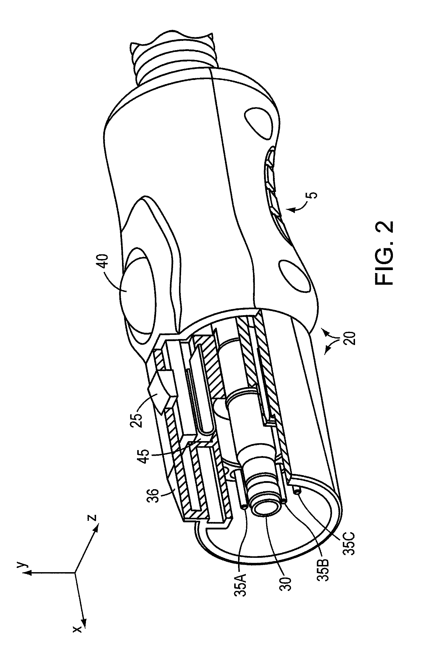
[0042]FIG. 1 is a drawing of a connector assembly 5, according to an illustrative embodiment. The connector assembly 5, which in some embodiments may simply be a connector, can be associated with and / or disposed relative to a torch for a thermal cutting system or welding system, such as a plasma arc system or a welding apparatus. The connector assembly 5 is configured to carry a gas and a current to the thermal cutting system or welding system (e.g., a plasma arc cutting torch, not shown) and mate with a corresponding connector assembly 10. In some embodiments, the corresponding connector assembly 10 is a socket disposed relative to a power and / or gas supply 15. The connector assembly 5 can slideably lock and mates with the corresponding connector assembly 10. The connector assembly 5 can disengage with a single actuation movement. In some embodiments, connector assembly 5 can be disposed relative to a power and / or gas supply 15 and the corresponding connector assembly 10 is dispose...


PUM

PropertyMeasurementUnit
timeaaaaaaaaaa
timeaaaaaaaaaa
timeaaaaaaaaaa

Abstract

A connector assembly for a thermal cutting system or welding system can include a housing having a locking device. The locking device can cause, upon application of a translational force, engagement of the connector assembly relative to a stationary receiving mechanism and can cause, upon application of a force on a contact member or a rotational moment on the contact member, disengagement of the locking device relative to the stationary receiving mechanism. The connector assembly can include a conduit disposed in the housing, the conduit carrying a gas to the thermal cutting system or welding system. The connector assembly can include a first current carrying member disposed in the housing, the first current carrying member carrying an operating current to the thermal cutting system or welding system and a second current carrying member disposed in the housing, the second current carrying member carrying a second current.

Description

FIELD OF THE INVENTION[0001]This invention generally relates to a connector assembly for a thermal cutting system or welding system. More specifically, the invention relates to a connector assembly for a plasma arc system or a welding apparatus.BACKGROUND OF THE INVENTION[0002]Welding and plasma arc torches are widely used in the welding, cutting and marking of materials. A plasma torch generally includes an electrode and a nozzle having a central exit orifice mounted within a torch body, electrical connections, passages for cooling, passages for arc control fluids (e.g., plasma gas), and a power supply. Optionally, a swirl ring is employed to control fluid flow patterns in the plasma chamber formed between the electrode and nozzle. The torch produces a plasma arc, a constricted ionized jet of a gas with high temperature and high momentum. Gases used in the torch can be non-reactive (e.g., argon or nitrogen) or reactive (e.g., oxygen or air). In operation, a pilot arc is first gener...

Claims


Application Information

Patent Timeline
Patent Type & Authority Patents(United States)
IPC IPC(8): H01R13/627
CPCB23K10/00B23K9/324
Inventor ROBERTS, JESSE A.
Owner HYPERTHERM INC
Why Eureka
Try Eureka