RF connector assembly

Active Publication Date: 2010-07-27
F TIME TECH INDAL
View PDF4 Cites 45 Cited by
  • Summary
  • Abstract
  • Description
  • Claims
  • Application Information

AI Technical Summary

Benefits of technology

[0012]The present invention has been accomplished under the circumstances in view. It is one object of the present invention to provide a RF connector assembly, which facilitates installation.
[0013]To achieve this and other objects of the present invention, a RF connector assembly comprises a male connector, and a female connector connected to the male connector for signal transmission. The female connector comprises an electrically insulative housing having a U-shaped locating groove upwardly extending around the periphery, a female connector terminal device inserted into the electrically insulative housing, and a U-clamp mounted in the U-shaped locating groove and partially extended to the inside of the electrically insulative housing to secure the female connector terminal device firmly in position.
[0014]To achieve this and other objects of the present invention, a RF connector assembly comprises a male connector, and a female connector connected to the male connector for signal transmission. The \male connector c

Problems solved by technology

However, because the locating groove is disposed inside the housing, it is difficult to set the clamp into position.
Fastening the two arms of the U-shaped clamp to the two sides of the locating groove is not easy.
More particularly, the small size of the housing makes the installation of the clamp more difficult.
Further, because the housing and the cl

Method used


Image

  • RF connector assembly
  • RF connector assembly
  • RF connector assembly

Examples


Example

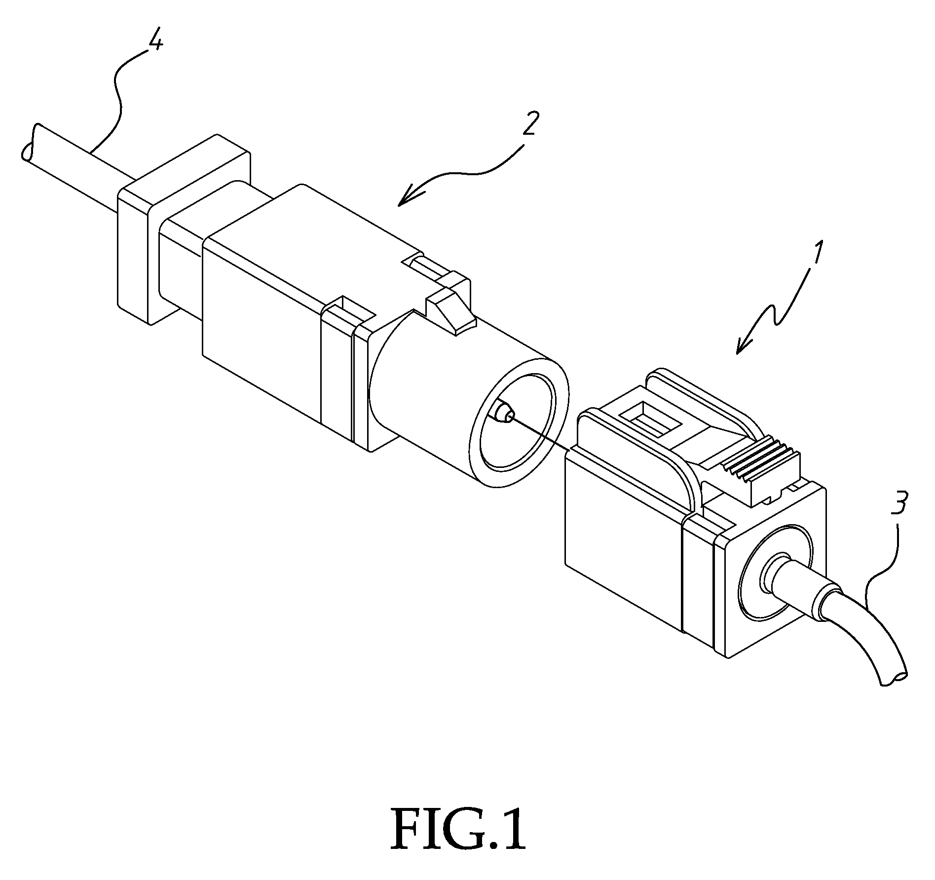
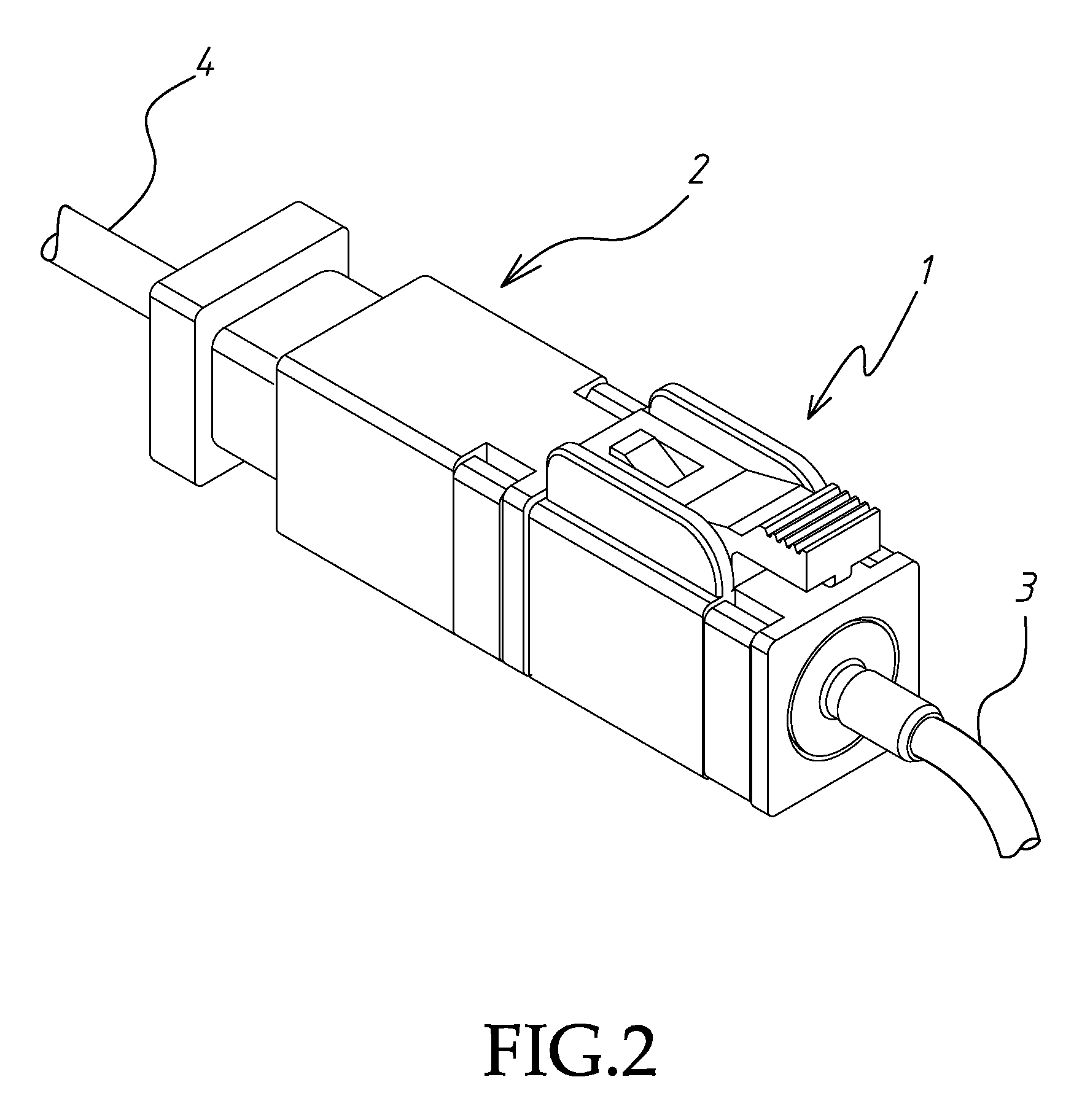
[0026]Referring to FIGS. 1˜3, a RF connector assembly in accordance with the present invention is shown comprising a female connector 1 and a male connector 2. When the female connector 1 and the male connector 2 are connected together, cable 3 and cable 4 (or a circuit board and a cable) are electrically connected for signal transmission.

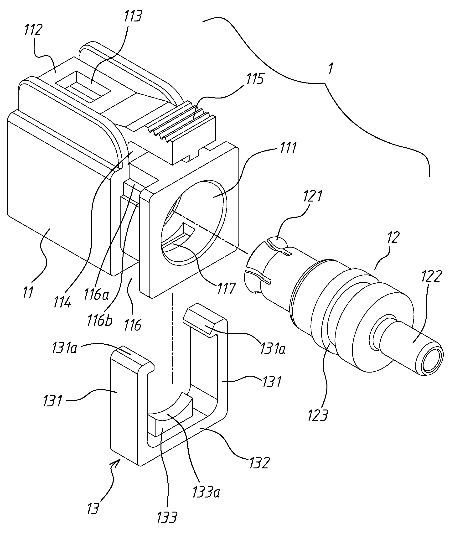
[0027]Referring to FIGS. 4˜6, the female connector 1 comprises an electrically insulative female connector housing 11, a female connector terminal device 12 and a U-clamp 13.

[0028]The electrically insulative female connector housing 11 is substantially a hollow rectangular shell having an insertion hole 111 extending through the front and rear sides thereof, a suspension frame strip 112 suspending at the top open side thereof and connected to the rear wall of the electrically insulative female connector housing 11 by a connection portion 114, a hook hole 113 defined in the frame strip 112, a handle 115 backwardly extended from the suspension frame ...


PUM


Abstract

A RF connector assembly includes a male connector, and a female connector connected to the male connector for signal transmission. The female connector and male connector each have a U-shaped locating groove upwardly extending around the periphery of the electrically insulative housing thereof, a connector terminal device inserted into the electrically insulative housing, and a U-clamp mounted in the U-shaped locating groove and partially extended to the inside of the electrically insulative housing to secure the connector terminal device firmly in position.

Description

BACKGROUND OF THE INVENTION[0001]1. Field of the Invention[0002]The present invention relates to an innovative design of RF connector assembly and more specifically, to the design of a U-shaped locating groove on the electrically insulative female connector housing or male connector housing and installation of a U-clamp in the U-shaped locating groove to secure the female connector terminal device or male connector terminal device inside the housing.[0003]2. Description of the Related Art[0004]A RF connector is adapted to connect two coaxial cables or one coaxial cable and one circuit board together for signal transmission.[0005]Basically, A RF connector is comprised of a female connector and a male connector. By means of forcing a hook hole at a locating plate of the female connector into engagement with a hook at the male connector, the male connector and the female connector are fastened together.[0006]Conventionally, the female connector and male connector each have an electrica...

Claims


Application Information

Patent Timeline
IPC IPC(8): H01R13/514
CPCH01R13/508H01R13/6272H01R24/50H01R2103/00
Inventor PENG, CHANG LIN
Owner F TIME TECH INDAL
Why Eureka
Try Eureka